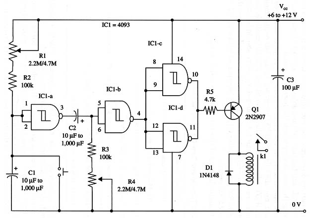
Circuit operation is as the other monostable projects described in this site using the 4093 IC, and the relay must be chosen according load requirements.
A mini DPDT relay such as the Radio Shack 275-259 controls small appliances rated to up than 1 A. Heavy-duty relays should be used to control more powerful loads, but if their coils are rated to more than 100 mA to 500 mA, transistor Q1 should be replaced with a TIP32, and R5 by a 2.2 kg resistor.
A schematic diagram of this timer is shown in Fig. 1.

Proper positioning of the polarized components (diode, transistor, and electrolytic capacitors) must be carefully observed.
The mini DPDT relay is mounted on the solderless board. If you’re using an equivalent, be careful with the terminals’ positions-they could be different.
The load is connected to the relay as shown in other projects in this timer series. R1 adjusts the first time delay, and R2 adjusts the second.
IC1- 4093 CMOS integrated circuit
Q1 - 2N2907 PNP general purpose silicon transistor
D1 - 1N4148 general purpose silicon diode
R1, R4 - 2,200,000 ohm to 4,700,000 ohm potentiometers
R2, R3 - 100,000 ohm, 1/4 W, 5% resistors
K1 - 6 or 12 V relay (see text), Radio Shack mini DPDT relay 27 5-249 is a
suitable unit
C1, C2 - 10 µF to 1,000 µF, 12 WVDC electrolytic capacitors
C3 - 100 µF, 16 WVDC electrolytic capacitor


