A possible application for this circuit is as signal injector, reaching channel 2 of the VHF TV band or even as a one channel CW remote control transmitter.
Adding a tone modulator, the circuit can be extended to a multi-channel remote control transmitter. The power supply can be from 2 to 4 AAA or AA cells or a 9 V battery.
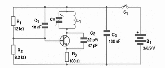
With higher voltage supplies and a 20 to 30 cm antenna, the range can be extended up to 50 meters. The tone signal can be applied to the circuit by a 10 nF to 100 nF capacitor connected to the transistor base or emitter, according to its amplitude. Figure 1 shows the schematics for this oscillator.

The circuit can be assembled using a printed circuit board (PCB) as chassis. The placement of the components on a PCB is shown in figure 2.

An option for the builder consists in the use of a solderless board or a universal printed circuit board or even a terminal strip, considering the circuit is not critical. The most important point to observe when assembling is keeping the wires and components’ terminals as short as possible.
The coil is formed by a number of turns that depends on the frequency range. It is wound using 18 to 22 AWG wire in a 1 dm of diameter core-less form. Use a pencil as reference to wound this coil. The number of turns is given bellow:
30 to 45 MHz—9 turns
45 to 60 MHz—6 turns
The trimmer capacitor can be of any type with maximum capacitance between 20 and 50 pF. C1 is a 47 pf ceramic capacitor for the range between 30 and 45 MHz and a 22 pF ceramic type for the 45 to 60 MHz range.
Testing the device is very easy. You just have to tune in a short wave radio near the oscillator and try to pick up its signal. The signal can also be picked up by a TV set tuned to channel 2 in the VHF band. When the trimmer reaches the frequency, the program in the tuned channel will disappear.
Competition:
- The Fox Hunter game can also be implemented with this oscillator used as transmitter. Use an 80 to 100 cm antenna to increase the range. The receiver must be short wave types or low band VHF, in order to pick up the signals.
- Use as a telegraph to practice coding and to make contests.
- Give a prize to the best assembly.
Semiconductors:
Q1—BF494 or equivalent—Silicon RF NPN transistor
Resistors: (1/8 W .or 1/4 W 5%)
R1—12 k ohm—brown, red, orange
R2—8.2 k—gray, red, red
R3—100 ohm—brown, black, brown
Capacitors:
C1—10 nF— ceramic
C2—22 pF to 47 pF—ceramic—see previous text
C3— 100 nF— ceramic
CV—trimmer capacitor—see previous text
Other:
L1—Coil—see previous text
S1—SPST—on/off switch
B1—3 to 9 V—AA cells or battery—holder or connectors
Terminal strip or printed circuit board, wires, solder, etc.


