Note: this project is part of my book Science Fair and Technology Education Projects published in USA.
This circuit can be used in demonstrations, science fairs or as an experimental alarm, protecting objects and places. Considering the electric current flowing to the body of the person is extremely weak, you can turn on an incandescent lamp plugged to the AC power line safely.
The used SCR (Silicon-controlled Rectifier) can control up to 300 W of loads powered by the 110/117/127 AC power line, but since it is an experimental project, we recommend to limit the load to 60 W. The circuit has some sensibility control, allowing the reader to adjust the trigger point, avoiding the erratic operation.
Important Note—2
As previously indicated, the circuit is safe due to the low current in the sensor, but it does not mean that the circuit does not need special care when assembled. The circuit is plugged to the AC power line, meaning that shock hazards are present.
How it Works
The core of the circuit is a SCR (Silicon-controlled Rectifier). The SCR is a semiconductor that triggers when a weak current is applied to its gate (G). A few microamperes are enough to trigger the SCR, making it conduct a higher current between its Anode (A) and Cathode (C or K).
This current is enough to turn on an incandescent lamp or to power a buzzer. For the TIC106 used in this project, the trigger current can be weak enough to cross the human body without causing any damage, sensation or shock. So, all you have to do is place a sensor in the gate and a lamp in the anode, powering the circuit from the AC power line, to have a touch alarm. The aim of the resistor is to limit the trigger current to a safe value that does not cause any sensation in the person who touches the sensor.
How to Assemble:
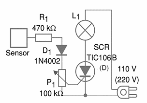
Figure 1 shows the schematic diagram of the alarm.

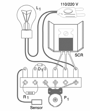
Figure 2 shows how the components can be soldered to a terminal strip. The circuit can also be assembled on a printed circuit board or using other technologies.

If you are plugging the device to a 110/117/127 AC power line, the SCR must be a “B” suffix. If you are plugging it to a 220/240 V AC power line, this component must be a “D” suffix.
If the load is a 40 W lamp or higher, the SCR must have a small heatsink. This heatsink consists in a metal plate bended to form a ‘U’. D1 is any general purpose diode. R1 can assume values in the range between 470 k ohm and 1 M ohm. You also can replace the trimmer Potentiometer by a common Potentiometer.
Testing and Using
In order to test, plug the circuit to the AC power line and touch the sensor, adjusting the sensitivity by P1 at the same time. The wire to the sensor is limited to 2 m, so it will not act as an antenna, picking hum that causes erratic triggering. Adjust P1 until you reach the trigger point. The sensor is a small metal plate 4 x 4 cm or larger. It is recommended to place the sensor on a plastic base.
If the lamp does not turn on when you touch and adjust P1, turn the position of the AC plug 180 degrees and try again. This is necessary to get the correct sense of the D1 polarization current.
Do not plug large objects to the circuit, because they act as antennas picking up undesirable currents and signals. These currents trigger the circuit without the need of any touch to the sensor, causing an erratic operation. Any object used to be a sensor (protected by the alarm) must be isolated from the ground. If you observe a light shock when touching the sensor, increase the value of R1.
What to Explain
Electric currents can pass across the human body and, in normal conditions, we are in contact with the ground. So, if we touch the sensor, a current can flow between the ground and the circuit passing through our body. This small current does not cause any shock sensation, but it is enough to trigger the circuit. Explain that this kind of circuit is used to control many types of domestic appliances.
Additional Works
Replace the lamp by a buzzer or other sound alarm. By doing that, the circuit can be used as a touch alarm, protecting objects or doors. A metal lock in a wooden door can be used as sensor. The alarm will trigger when someone touches the lock.
Competition
- Plug the alarm to several objects placed on a table. Each competitor has to remove one object at a time, without triggering the circuit. Each competitor that triggers the alarm is out. The winner is the last to remove an object.
SCR—TIC106B or D—Silicon Controlled Rectifier—see text
P1—100 k?—trimmer Potentiometer or common Potentiometer
R1—470 k ? x 1/8 W—resistor—yellow, violet, yellow
D1—1N4002 or equivalent—silicon diode
L1—5 to 60 W—incandescent lamp according the local AC power line voltage
Other:
Terminal strip or printed circuit board, power cord, socket for the lamp, plastic box to house the circuit, sensor, wires, solder, etc.


