Measuring the current or the voltage in a circuit allows us to determine if the circuit is good or bad. In some cases, measurements can also determine the cause of a problem. Many electronic devices can be tested with some simple resistance measurements.
Analog Multimeters
There are two types of multimeters an electrician can purchase to work on not only electric installations, but also on analog and digital electronics. The analog multimeter is formed by a moving coil meter (microamperimeter) and circuitry with functions selected according the quantities to be measured.
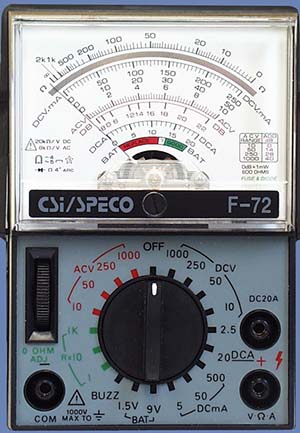
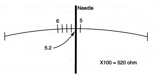
For example, if a reader must measure resistances he needs to select one of the resistance positions on the switch according to the expected value. If the position Ω x100 is selected, the values read in the scale must be multiplied by 100. An indication of 5.2 as shown in Figure 2 indicates a resistance of 520 Ω.
The selection of the quantity to be measured is made by a switch or selected by jacks where the probes are connected. Figure 1 shows this kind of multimeter. The most important specification of an analog multimeter is its sensitivity. The analog multimeter, when measuring voltages, needs power to move its needle.
The power comes from the circuit being measured. This power alters or “loads” the multimeter changing the value reading. The better the multimeter, the lower the load needed from the circuit to be measured, meaning a better multimeter can pick up lower voltages.
The sensitivity of an analog multimeter comes from its internal resistance when measuring a voltage (it is associated to the sensitivity of the moving coil meter). This value is indicated in ohm per volt (Ω /V) and should be as high as possible. Less expensive multimeters have a sensitivity of around 1000 ohm per volt. Better multimeters have a sensitivity of 10,000 Ω per volt or more.
When using a low-sensitivity multimeter, an electrician must take care to not be tricked by the voltages indicated when measuring high-resis- tance or high-impedance circuits. These are circuits where the presence of the instrument can cause great alterations in the voltage measured.
This occurs because the presence of the multimeter loads the circuit.
Digital Multimeter
Many low-cost digital multimeters are available today. Although by many aspects they are better than the analog type, some functions or measurements exist where the analog multimeter is the better choice. For the reader who is not familiar with multimeters, using this type of tool is not recommended as a starting point. When beginning, it is easier to use the analog type.
The digital multimeter is formed by an electronic circuit that presents the results of the measurements in a liquid crystal display (LCD) like the one shown in Figure 3.
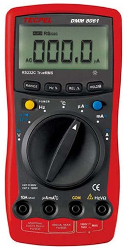
The functions for measurement using a digital multimeter are the same as analog multimeters.
Because the digital multimeter uses an internal power supply (normally a 9V battery), it doesn’t need to extract large amounts of energy from the circuit
Where the voltages must be measured as the analog multimeter does. This means that the circuit being tested interprets it as a very high-impedance load not causing significant changes in the quantity to be measured. The problem of inaccuracy found in analog multimeters when measuring low voltages in high-resistance circuits doesn't exist in the digital types.
How to Use a Multimeter
Voltage measurements.
Readers must take care not to overload the instrument when measuring voltages. This can cause damage including burning it. They must also differentiate the points where AC and DC voltages are found.
When measuring a DC voltage, place the function selection switch in the scale that gives you a comfortable reading of the expected voltage. For example, if you are expecting a reading of about 12V in a circuit, place the switch in the position 0-15VDC. The position O-15oVDC is not recommended because with 12V, you would have a small deflection of the needle.
Observing the poles, place the probes in the circuit to be measured. If you invert the probes or the poles are different from what is expected, the needle tends to move in the wrong direction, indicating something less than zero. If this happens, invert the probes to correct the reading. Some instruments have a pole switch that inverts the probe connections without moving them. Figure 4 shows how the multimeter is used to measure a DC voltage in a circuit.
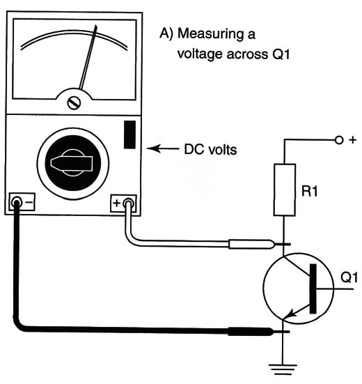
This process is for digital and analog meters. Some digital multimeters indicate the value with a “-” sign if the voltage is negative or if the probes are inverted. If you have no idea about the voltage present in a circuit, begin by using a higher scale.
Current measurements
Current measurements are not very common when working with electronic circuits because the circuit where the current ÍS measured must DQ interrupted to place the multimeter's probes (Figure 5).
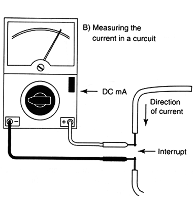
When measuring DC currents, polarity must be observed when positioning the probes. It is very important to choose the correct scale when measuring currents. If a low-current scale is chosen in a high-current circuit, the meter can be damaged or the internal fuses can burn.
Use the higher current if you have no idea about the value of a current to be measured in a circuit. The procedure is the same whether using a digital or analog multimeter. In some cases the multimeter has a self-adjusting scale and no switch is necessary for this task.
Resistance measurements
The resistance measurement and the continuity test are the most common in normal work with electronics. To run a resistance test, apply a voltage to the circuit or device to be measured. The magnitude of this current causes the multimeter to display the value of its resistance.
Analog multimeters use an internal cell (normally a 1.5V AA cell) and digital multimeters use a 9V power supply. As the batteries in a multimeter lose power, so does the multimeter. Before each use, analog types must be adjusted to zero. This adjustment is shown in Figure 6.
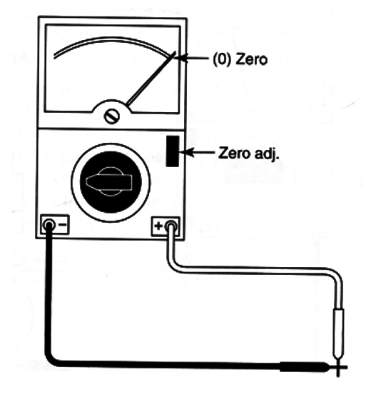
Place the probes together and adjust the “zero adj” potentiometer until the needle in the scale indicates zero. After this procedure you can use the multimeter to measure resistance.
Choose the appropriate scale for the resistance you expect to measure. A better reading is one made from the central region to the right extreme.
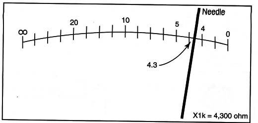
For instance, if you place the switch in the Ω x tk scale, it means you have to multiply the readings by 1000. Figure 7 shows that an indication of 4.3 in this scale means you are measuring 4300 Ω.
Other Multimeter Functions
Many multimeters can measure other quantities besides resistance, currents, and voltages. Multimeters with battery test scales, decibels, continuity test function, diode test, and transistor test are common.
Reading and Interpreting Multimeter Values
Knowing that placing the probes of a multimeter in the terminals of a component and having it give you a reading either with a needle or LCD is not enough. You need to know what the reading means to conclude something of value.
Some components are good when they present high resistance (capacitors, reverse-biased diodes, open switches, etc.) and some components are good with the reverse indication-when they present low resistance (fuses, wires, direct-biased diodes, coils, etc.).
At the end of the description of each component, the text explained how to test many components using a multimeter. When measuring voltages in a circuit, you must take care with interpretation of the values. Although the schematics indicate some voltages, depending on the multimeter, the presence of the multimeter in the circuit can change the values and give a false reading (mainly in less expensive analog types).
Don't trust your multimeter! You must be sure that your multimeter can measure the indicated voltage in a circuit.


