Many workshops also work with devices that have more than 10 years of use, needing repair them.
Get certain components for these devices is problematic because many are no longer manufactured.
However, there are many devices that have been discarded because they have a problem that could not solve, precisely because there onlu one damaged component, but other components can be removed.
There may also be cases where the damages that a device has to be such that not worth investing too much in replacing a part, in which case try to repair, even if precariously.
In our book Fix All (In portuguese) we give various techniques for doing so such as, for example, the repair of cracked plastic boxes that can be made with the help of a hot soldering iron, as shown in figure 1.
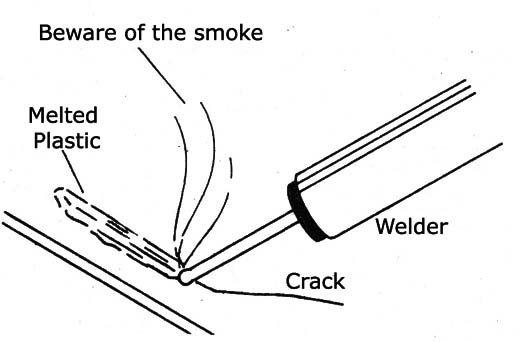
In this case, they can "solder" the plastic as shown in the figure, an operation that should be done in a well ventilated place, because the vapors should not be inspirated.
Having made this soldering operation, the tip of the soldering iron must be cleaned so that it can be used again in its normal function.
Component Recovery
Many components do not deteriorate with time and, therefore, can be reused with full reliability.
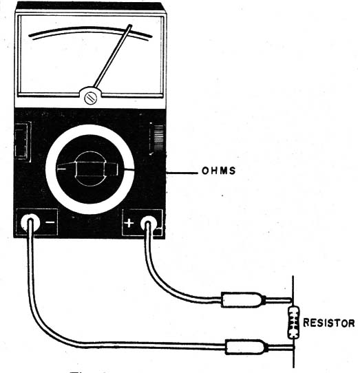
The resistors can be tested with the multimeter before being stored in a box of scraps to use.
The test consists of measuring its resistance, as shown in Figure 2.
For electrolytic capacitors the use is problematic because they tend to run out (dry) with time, but for other capacitors a test on a simple oscillator, as shown in Figure 3, can be done.
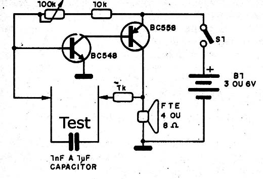
If the circuit "beep" when we set the pot, it is a sign that the capacitor is in good condition, if greater than 10 nF.
The diodes can be utilized provided that they present high leakage.
In Figure 4 we show how to check the leakage of a diode with the multimeter in the highest range of resistances.
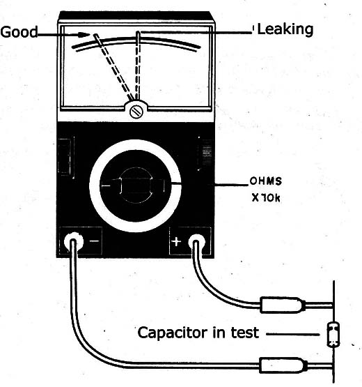
The reverse resistance should be more than 50k for rectifier diodes and greater than 100 k to other types of diodes.
To extract integrated circuits from printed circuit boards see figure 5.
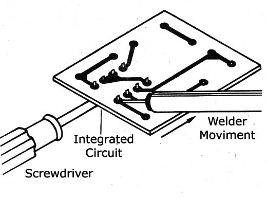
We slide tue tip of aoldering wiring removing solder from the copper side to release them from the board all at once, and with a screwdriver go forcing the component output.
To facilitate extraction of circuits based DIL packages we can rely on a special desoldering tip adapted to a common soldering iron as shown in Figure 6.
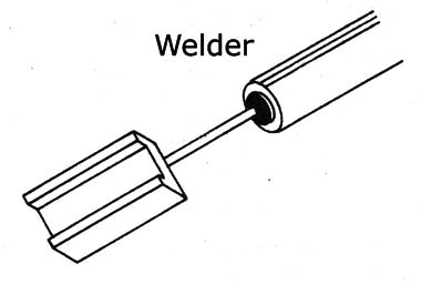
Another useful tool for dismounting boards and recovery components is the solder sucker shown in Figure 7.
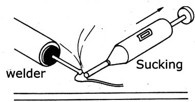
This tool has a small pump that sucks the solder when it is melted, thus freeing the component terminal that should be removed.
Some types, as shown in Figure 8, are already mounted in the soldering iron itself.
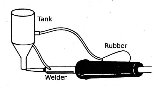
Is also useful as an absorbent mesh with the solder removal tool as shown in Figure 9.
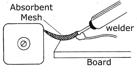
Just warm this mesh in contact with the tip of the soldering iron where the solder should be removed and remove it when still warm.
On the website, we also have a good amount of articles on the subject, especially in instrumentation section.
If you have skills and likes to fix things, see these articles and it is not difficult to become a technician or repair man and open a small workshop.


