Undoubtedly, the use of embedded Linux makes life easier for those who develop several products and devices. Using an operating system of the type, it is possible to have support for different connectivity available (wifi, Bluetooth, Ethernet etc.), support for the creation of very rich graphical interfaces and everything else a personal computer can offer.
The great advantages here are due to offering the same computational power as a personal computer with the ease of having a small size, low electricity consumption and a very good cost / benefit ratio.
Given the importance and versatility of Linux embedded in current technology, this article will teach one of the most basic and important tasks of a system with embedded Linux which must interact with external circuits: control of GPIOs by the command line. To make learning more accessible, the popular Raspberry Pi will be used as hardware, triggering a relay.
NECESSARY MATERIAL
To follow the steps in this article, you will need:
One Raspberry Pi board, of any model. This article will use the Raspberry Pi 3B board for reasons of popularity / availability to purchase it.
One micro-SD card of at least 8GB
One 5V / 3A switching power supply, with micro-USB connector
Protoboard (400 points)
One relay with 5V coil voltage
One 1N4007 diode
One 100k? / 0.25W resistor
One 10k? / 0.25W resistor
One FQP30N06L transistor (N channel MOSFET)
Male-male and male-female jumpers
PREREQUISITES
This article assumes that your Raspberry Pi is already operational, that is, with a Linux operating system (Raspberry Pi OS or Raspbian) already installed and network connectivity working.
If you don't know how to do this, read this article that explains in detail how to prepare your Raspberry Pi for use.
GPIOs at Raspberry Pi
Initially, you need to know what a GPIO is. The acronym GPIO refers to General Purpose Input / Output. A GPIO consists of a microcontroller / SoC / SIP pin which can be configured to operate as a digital input or digital output. That is, pins with the GPIO designation can work as a digital input or output for your project, according to your need.
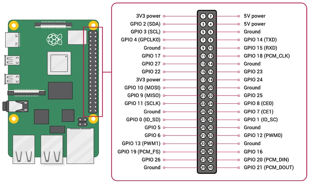
Raspberry Pi offers a 40-pin expansion header, among which are GPIOs that the user / developer can freely use for their projects. This header is the same for all the latest Raspberry Pi (most present on the market), except for the first ones produced, where 26 pins were used only in the expansion header. See Figure 1 for the location of this header and what each of the 40 pins has in function.

In Figure 1, it is possible to see that, among the pins present, some have the functionality of GPIOs. These are the ones we can use in the example / experiment in this article (triggering a relay).
ATTENTION POINTS
Raspberry Pi GPIOs have some points of attention, as described below. Failing to obey them means taking a great risk of destroying your Raspberry Pi.
1. Voltage level: Raspberry Pi GPIOs work with a maximum voltage level of 3.3V, not tolerant to 5V.
2. Output current (GPIOs configured as output): Raspberry Pi GPIOs configured as output can deliver a maximum of 16mA of current, with the maximum current supplied by all GPIOs in output mode must not exceed 50mA. Thus, it is highly recommended to use circuits such as opto-couplers or current boosts (with BJT or M-channel MOSFET transistors) in such GPIOs, to use the lowest possible electric current from them.
GPIOs on embedded Linux
Linux has a framework dedicated to the access and control of GPIOs, called the GPIO framework (its complete documentation can be accessed by clicking here). This framework provides access to GPIOs by sysfs, accessible by command line, from files in the /sys/class/gpio directory. This means that, in embedded Linux, the use of GPIOs (writing and reading) is made from writing and reading files in these directories.
So, the first thing to do before handling GPIOs is to go to the GPIOs directory in syfs: /sys/class/gpio. To do this, use the command below:
cd /sys/class/gpio
To use a GPIO on Linux, whether for writing or reading, you must first export it to the user. This is done by writing the desired GPIO in the file /sys/class/gpio/export. Assuming you are already in the /sys/class/gpio directory, to use GPIO 17, for example, use the following command:
echo 17 > export
That done, the gpio17 directory will appear inside /sys/class/gpio. This directory will contain all files for configuring and using GPIO17. To access this directory, use the command below:
cd /sys/class/gpio/gpio17
The GPIO17 operating mode is defined in the direction file, contained in the GPIO17 directory (cd/sys/class/gpio/gpio17). This mode of operation can be:
in: in this operating mode, the GPIO will be configured as a digital input.
For example: to configure GPIO17 as a digital input, assuming you are already in the /sys/class/gpio/gpio17 directory, use the command below:
echo “in” > direction
out: in this operating mode, the GPIO will be configured as a digital output.
For example: to configure GPIO17 as a digital output, assuming you are already in the /sys/class/gpio/gpio17 directory, use the command below:
echo “out” > direction
At this point, you have already defined the GPIO17 operating mode. We will now learn how to write (mode: digital output) and read (mode: digital input) GPIO17.
In the digital output operation mode (out): to write the GPIO17, that is, make the GPIO17 header pin have a high (3.3V) or low (0V) logic level, use the value file, contained in the /sys/class/gpio/gpio17 directory.
For example, to make the GPIO17 pin have a voltage of 3.3V, assuming you are already in the /sys/class/gpio/gpio17 directory, use the command below:
echo 1 > value
To make the GPIO17 pin have a voltage of 0V, assuming you are already in the /sys/class/gpio/gpio17 directory, use the command below:
echo 0 > value
In digital input operating mode (in): to read the GPIO17, that is, to know whether the header pin corresponding to the GPIO17 has a high/1 (3.3V) or low/0 (0V) logic level, assuming you are already in the /sys/class/gpio/gpio17 directory, use the command below:
cat value
The command response will be the logic level (0 or 1) present on the header pin corresponding to GPIO17.
Activating a relay via the command line on embedded Linux
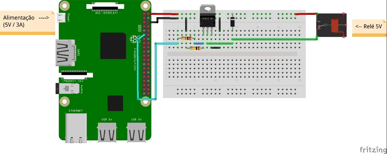
Now, let's put into practice the manipulation of GPIOs on Linux by activating a relay via the command line on embedded Linux. To do this, first you need to assemble the schematic circuit shown in Figure 2. Note that, as in the previous examples, here we will use GPIO17 to control the relay.
Once the schematic circuit of Figure 2 is assembled, we can proceed to activate the relay itself. For this, at the terminal, configure the GPIO17 with digital output operation mode. To do this, use the commands below:
cd /sys/class/gpio
echo 17 > export
cd gpio17
echo “out” > direction
That done, the GPIO17 is ready to control the relay. To activate the relay, use the following command:
echo 1 > value
And to deactivate the relay, use the command below:
echo 0 > value
You can connect a load (AC or DC circuit) at the relay output and see that load being activated or deactivated by means of commands made on the embedded Linux command line. In this way, we demonstrate the control of several GPIO loads on the Linux command line, using a Raspberry Pi card as hardware.
Last step - release of GPIO for use
On embedded Linux, when you export from GPIO (as shown in the “GPIOs on embedded Linux” topic of this article), you “book” GPIO for you (user), not allowing other users to access GPIO while you use it . Thus, after using the GPIO, it is necessary to release the GPIO that you used so others can have access. This procedure is called unexport.
To make this release, considering the same GPIO17 as the previous examples, use the command below:
echo 17 > /sys/class/gpio/unexport
You will notice that the gpio17 directory (located inside the /sys/class/gpio directory) will disappear. This means that you (your Linux user) no longer have the power to use this GPIO and that it can be used by other users.
Conclusion
In this article, we saw what GPIOs are on embedded Linux, by the command line. In addition, you have learned how to use a GPIO as a digital input or output, according to the needs of your project.
To demonstrate the content learned, a simple but very useful experiment was carried out: the activation of a relay by GPIO, from the command line. With this experiment, you can drive any DC or AC loads which are within the operating limits of the relay used. This allows a Raspberry Pi to control from small to large loads. This type of approach opens up different possibilities for projects and applications, both for testing and experimentation purposes and for automation purposes.


