Rear collisions are one of the most common types of traffic accidents that occur on roads around the world. The most frequent reason for such accidents is precisely the incorrect positioning of the vehicle in relation to the vehicle in front, without a minimum safety distance being kept.
A rear collision caused by insufficient distance is a type of accident caused mainly by the driver's action. In this case, prevention depends little on the state of the vehicle, the condition of the road or the adequacy of the signage, but it depends mainly on the awareness of the driver.
This project features a didactic braking distance simulator to be used in science fair demonstrations by elementary and high school students. Due to its visual appeal, the simulator is intended to be used in traffic awareness campaigns. The challenge is to maintain a minimum safety distance from the vehicle in front in order to be able to stop without causing a collision in case of sudden braking.
The simulator was designed with inspiration from the Open LED Race project, an open source “maker” initiative. The electronics are based on an Arduino UNO system, which is easy to obtain and relatively low cost. The visual element is a WS2812 or WS2813 standard addressable RGB LEDs strip of any number of LEDs. Finally, to facilitate strip control, the Adafruit NeoPixel library was used.
How it works
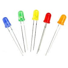
An LED, which stands for Light Emitting Diode, is an electronic component that emits light when properly energized. The light produced depends mainly on the chemical elements used in the construction of the component.
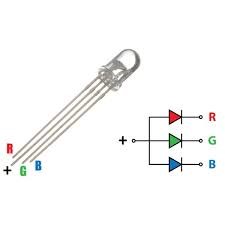
An RGB LED - Red-Green-Blue LED - is a special type of LED that has the three basic color components in a single casing. Depending on the voltages applied between the terminals, the LED emits light in the equivalent color.
In turn, a strip of LEDs is nothing more than an association of LEDs in parallel. With them it is possible to obtain very interesting lighting effects. Such strips are commercially available with LEDs of various colors, including RGB LEDs, so that the strip color can be customized.

More recently, addressable RGB LEDs strips have being available on the market, which combine the effects obtained with RGB LEDs and a certain form of automation, so that each LED can be configured to glow in a certain color, independently of the others. The most popular strips are in the WS2812 or WS2813 standard.
Most addressable strips have three connections: one terminal for positive voltage supply, another common terminal, and a third special terminal for data connection. These strips require, in addition to the electrical supply, a digital controller. The basic operation consists of using a controller to send packets of information in digital format through the logical terminal of the strip. The data packets must contain, in a simplified way, the LED address in relation to the beginning of the strip, the red-green-blue color components and the respective intensities.
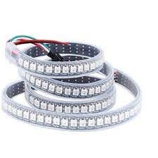
Each manufacturer has its own controllers for their strips, but many manufacturers follow the WS2812 or WS2813 standards so that their controllers and strips are interchangeable. This also facilitates programming in case of devices like Arduino. In such scenario, there are several function libraries readily available that make the work easier, such as the famous Adafruit NeoPixel.
Parts list
The parts used in this project were:
• Elegoo UNO R3 (Arduino compatible)
• Chinly WS2812B LED Pixel Strip (144 LEDs)
• Amazon Basics Wall Charger 5V (2A USB charger)
• Arduino IDE 1.8.19
• Adafruit NeoPixel 1.10.3
• 440 ohms 1/4W resistor
• Miscellaneous: breadboard, switches, jumpers, connectors...
Assembly
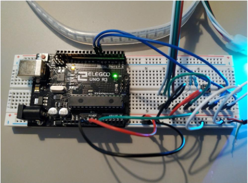
The figure below shows the electronic circuit assembled on a breadboard. The speaker is optional and has not been used.
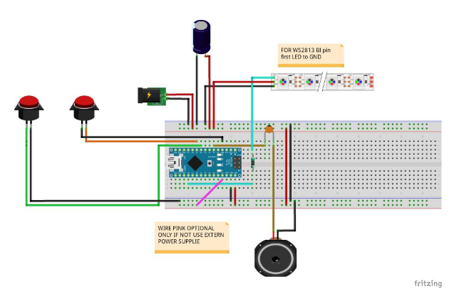
Before uploading the source code in Arduino, you must install the Adafruit NeoPixel library as shown in the figures below.
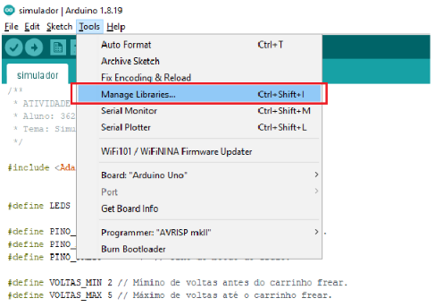
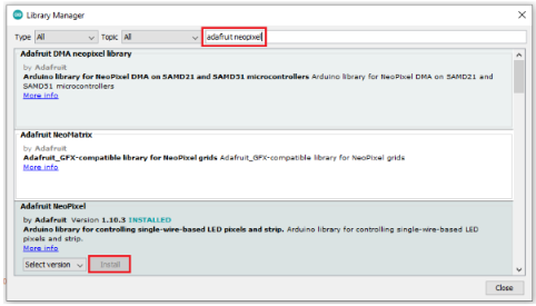
When you upload the source code, Arduino starts running it automatically. Repeatedly press the buttons to accelerate or brake the vehicle.
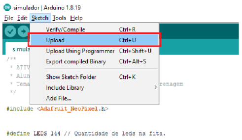
Proof and use:
After the source code is uploaded, the Arduino can be disconnected from the computer. The circuit can then be supplied with a 5V source capable of providing enough current to the LEDs. In the case of this simulator, as only two or three LEDs will be lit simultaneously, an ordinary USB charger is enough.
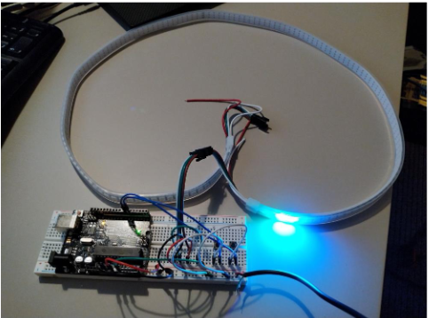
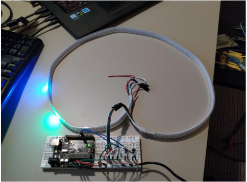
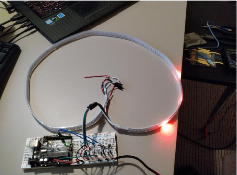
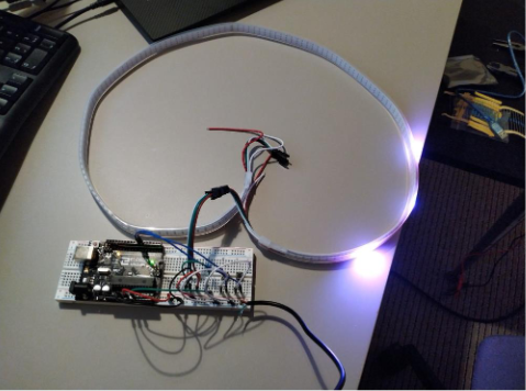
The simulation starts with the vehicles positioned at the beginning of the strip. No vehicle moves until a button is pressed. Repeatedly press the accelerator or brake to change vehicle speed. The simulation ends if the vehicles collide or if they both stop without colliding. A visual effect is shown and the simulation automatically restarts after five seconds.
References
MAKER SOCIETY, Open LED Race Project, https://openledrace.net/, accessed 08/12/2021.
ARDUINO, Arduino, https://www.arduino.cc/, accessed 22/12/2021.
ARROW, Protocol for the WS2812B Programmable LED, https://www.arrow.com/en/research-and-events/articles/protocol-for-the-ws2812b-programmable-led, accessed 22/12/2021.
Source-code
#include
#define LEDS 144 // Number of LEDs.
#define PIN_LEDS A0 // Track data pin.
#define PIN_ACCELERATOR 6 // Accelerator pin.
#define PIN_BREAK 7 // Break pin.
#define LAPS_MIN 2 // Minimum laps before break.
#define LAPS_MAX 5 // Maximum laps to break.
#define FACTOR_ACCELERATION 0.1 // Acceleration factor.
#define FACTOR_BREAKING 0.05 // Breaking factor.
#define MAXIMUM_SPEED 0.15 // Maximum speed.
#define PAUSE 5 // Refresh rate.
float speed_1 = 0;
float speed_2 = 0;
float distance_1 = 0;
float distance_2 = 0;
int laps_completed = 0;
long distance_random = 0;
byte flag_accelerator = 0;
byte flag_break = 0;
Adafruit_NeoPixel track = Adafruit_NeoPixel(LEDS, PIN_LEDS, NEO_GRB + NEO_KHZ800);
void setup()
{
track.begin();
pinMode(PIN_ACCELERATOR, INPUT_PULLUP);
pinMode(PIN_BREAK, INPUT_PULLUP);
simulation_start();
}
void simulation_start()
{
for (int i = 0; i < LEDS; i++)
track.setPixelColor(i, track.Color(0, 0, 0));
speed_1 = 0;
speed_2 = 0;
distance_1 = 1;
distance_2 = 0;
laps_completed = 0;
distance_random = random(LEDS * LAPS_MIN, LEDS * LAPS_MAX);
flag_accelerator = 0;
flag_break = 0;
}
void loop()
{
for (int i = 0; i < LEDS; i++)
track.setPixelColor(i, track.Color(0, 0, 0));
if ((flag_accelerator == 1) && (digitalRead(PIN_ACCELERATOR) == 0))
{
flag_accelerator = 0;
speed_1 = MAXIMUM_SPEED;
speed_2 += FACTOR_ACCELERATION;
}
if ((flag_accelerator == 0) && (digitalRead(PIN_ACCELERATOR) == 1))
flag_accelerator = 1;
if ((flag_break == 1) && (digitalRead(PIN_BREAK) == 0))
{
flag_break = 0;
speed_1 = MAXIMUM_SPEED;
if (speed_2 >= FACTOR_BREAKING)
speed_2 -= FACTOR_BREAKING;
else
speed_2 = 0;
}
if ((flag_break == 0) && (digitalRead(PIN_BREAK) == 1))
flag_break = 1;
if (distance_1 >= distance_random)
speed_1 = 0;
distance_1 += speed_1;
distance_2 += speed_2;
if (distance_2 > distance_1)
{
track.setPixelColor(10, track.Color(255, 0, 0));
track.setPixelColor(20, track.Color(255, 0, 0));
track.setPixelColor(30, track.Color(255, 0, 0));
track.show();
delay(5000);
simulation_start();
}
if (distance_1 > LEDS * laps_completed)
laps_completed++;
if ((laps_completed > LAPS_MIN) && (distance_2 > 0) && (speed_2 <= 0)) {
track.setPixelColor(10, track.Color(255, 0, 255));
track.setPixelColor(20, track.Color(255, 0, 255));
track.setPixelColor(30, track.Color(255, 0, 255));
track.show();
delay(5000);
simulation_start();
}
if (distance_1 >= distance_random)
track.setPixelColor(((word)distance_1 % LEDS), track.Color(255, 0, 0));
else
track.setPixelColor(((word)distance_1 % LEDS), track.Color(0, 0, 255));
track.setPixelColor(((word)distance_2 % LEDS), track.Color(0, 255, 0));
track.show();
delay(PAUSE);
}


