The idea of being able to amplify electrical signals is not new. It existed long before the valves and even before the radio era began.
According to old documentation, the idea of having a component with which it would be possible to control enormous electric powers from small intensity signals was already studied in 1888. However, the term amplifier was not yet used.
The idea was to use saturable cores to control electrical machines, mainly machines for heavy use, as with equipment used on ships, made since 1900.
With the arrival of valves, research into using magnetic cores for the development of control circuits was diminished, as the valves seemed to perform better in this purpose.
The research done at the time shows that, according to what was found, the Germans invented the magnetic amplifiers, but today, this invention is credited to the Americans. The discovery of selenium rectifiers seems to have contributed to the expansion of the use of these amplifiers.
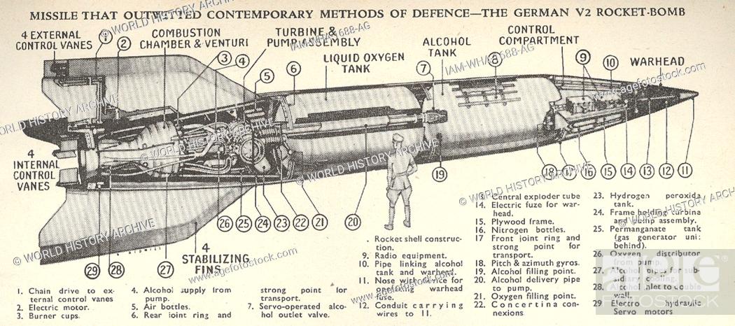
The fact is that the Germans used magnetic amplifiers in the first half of the last century in stabilizer systems for cannons, autopilots, motor controllers, missiles, including the stabilizer control and of the famous V2 flying bomb. (Figure 1)
It is reported that the civilian applications of magnetic amplifiers also spread to computers, trucks, locomotives and even in control of transmission lines involving electric powers that reached 50,000 kVA.
It is also reported that, from the beginning of the century to the 1950s, many countries made efforts to develop technologies with this type of component that did not use vacuum tubes or semiconductor materials.
It is said that the German efforts in World War II to develop this technology were due to the fragility of the valves and their lesser durability compared to magnetic amplifiers. During World War II, the Americans resumed research with this technology, even using them in radar, computers, and other circuits.
But what is a magnetic amplifier after all? Is it a component of a disruptive technology that can still be used today?
The Magnetic Amplifier
To understand how this type of component works, we can start from an analogy with hydraulic systems.
We can control a flow of water capable of exerting enormous pressure through a valve that can be activated with little pressure, as shown in Figure 2.
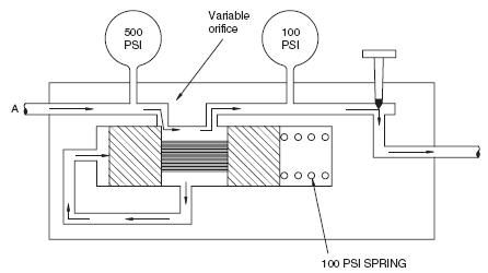
With a little pressure, we can then control a flow with a much higher pressure. It is according to this principle that the cars hydraulic brakes work.
But, we can transfer this principle to electronic circuits, starting with a simple alternating current configuration shown in Figure 3.

If we have a coil in series with a load, as shown in the figure, we know that the coil's inductance will represent an opposition to the current flow that reaches the load.
With greater inductance, we have less power in the load, and with less inductance, we have more electric power.
But the important thing is that we can control this inductance by moving a core inside the coil. Thus, we can control the power applied to the load with little effort, representing an output power gain.
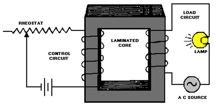
In this case, we have control by the presence of the core, with its movement. In other words, we control the electric current with a mechanical force. However, in a more efficient application, we can use a fixed core and control the core permeability through a field created by a control coil, as shown in Figure 4.

Thus, with a smaller current flowing in a control winding, we can control a much larger current to be applied to a load if we use a saturable core.
The relation amperes/spirals of the control winding and amperes/spirals of the load winding give the gain of this amplifier circuit.
Of course, we can also think about applying a direct current circuit to the load, coupling a rectifier diode, as shown in Figure 5.

Of course, this is a simplified theoretical circuit. In practice, some problems may occur.
One of the problems is that if we look at the circuit, we see that it is a transformer and that the current flowing in the load winding can induce a high voltage in the control winding, capable of affecting the input circuit.
Thus, we can start from the primary circuit and improve by adding feedback, as shown in figure 6.
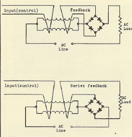
Very high-power gains can be obtained in such a circuit. They can go over a million times.
In Figure 7, we have a circuit that shows how we can use a magnetic amplifier to control a motor's speed and reverse its direction of rotation.
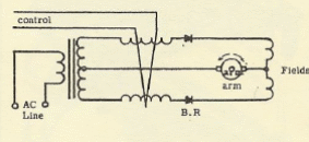
A simple circuit used in educational applications is a dimmer or power control for an incandescent lamp.
In a 1957 publication, we found a magnetic amplifier that used a new component, a saturable reactor, which was used in a simple power supply for polarization, shown in a Radio News magazine at the time. The circuit is shown in Figure 9.
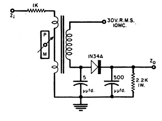
And, more complex things could be created, like the monostable multivibrator shown in Figure 10.
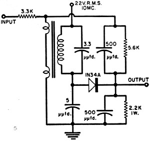
Yet another fascinating practical circuit found in documentation is a circuit that uses a coal microphone to modulate a Tesla coil.
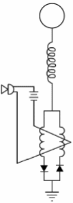
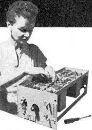
In the photo in Figure 12, an old small magnetic amplifier. Gigantic units used in industries existed in the years before 1950.
References: US Navy (1951) – High Voltage Press - 2000

