A capacitor is a simple capacitor, but an electrolytic capacitor is more than that. Involving chemical reactions and a volatile substance in its interior, this component has a behavior that goes beyond the ordinary and requires extreme care and knowledge by those who use it.
Based on extensive technical literature that we have collected on the internet, we focus on some critical points for those who use this type of component, whether in design, maintenance or simply because they want to take advantage of one of them stored in their scrap box.
The types
Although the working principle of electrolytic capacitors is the same, a bed of metal oxide such as aluminum, tantalum or niobium leads to somewhat similar behavior. For our analysis, we will focus on the most common type that is the aluminium one.
In Figure 1, we have the physical model and the equivalent circuit to a flat electrolytic capacitor.
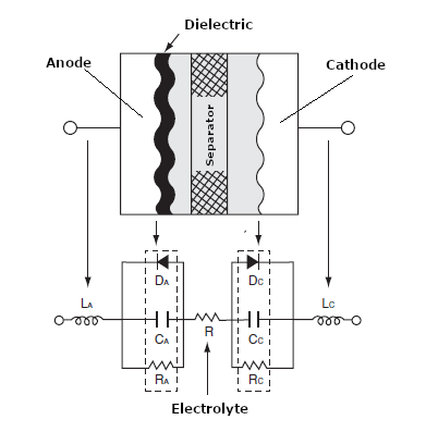
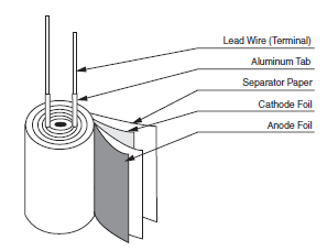
Note the associated resistances and capacitances. But, an interesting point that makes us suspect something is different in this component is that there is an equivalent diode, and a diode is a polarized component. In practice, the electrolytic capacitor is not flat. It has a tubular structure that adds inductance to it. We then have the basic structure of this component in the tubular form shown in Figure 2.
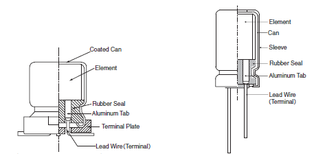
SMD and parallel terminal types.
We will not be concerned with how they are manufactured but with the characteristics that lead to their behavior.
Thus, as we know, the capacitance of this component is due to the very thin layer of aluminum oxide that forms on an aluminum sheet. This Al2O3 layer functions as a dielectric and also provides the component with rectifying properties. Thus, its characteristic curve is that of a diode, as shown in Figure 4.
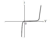
That shows why these components must not be inverted and cannot work directly with alternating currents.
Characteristics
The electrolytic capacitor is manufactured to work as a capacitor and, therefore, must have a capacitance within certain operating conditions and work with specific voltages and types of signals.
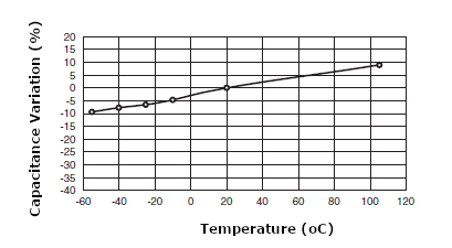
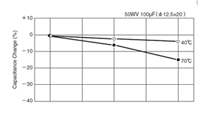
The first characteristic of this component, which perhaps many do not know, is that the capacitance of an electrolytic capacitor varies significantly with temperature. A curious fact is that, while in many components, the characteristics deteriorate, in the electrolytic capacitor, we can say that it works the other way around with temperature. When the temperature increases, its capacitance also increases, as shown in Figure 5.
Another characteristic of little knowledge is that related to the variation of the leakage current with time.
When we apply a direct voltage to an electrolytic capacitor to charge it, a small leakage current flows through the dielectric. This leakage current is not constant. Initially high, it decreases with time and stabilizes after a few minutes of operation. Note that this is not the charging current of the capacitor. It is measured immediately after the capacitor has finished charging. In Figure 6, we show this curve.
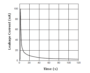
The leakage current also varies with temperature and increases with it.
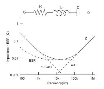
Another behavior of the electrolytic capacitor that needs to be taken into account by those who use it is how it reacts to a signal. As shown in Figure 6, the circuit equivalent to this component is an RLC-series, as shown in Figure 7. Thus, we find in its characteristic a point where its impedance is low.
Reliability and durability
Due to its characteristics as a component with the chemical-based operation, the electrolytic capacitor is perhaps the one that is subject to the highest failure rate and therefore, there is a need to take special care with it.
Thus, an interesting curve that those who use this type of component in projects should be noted is the "bathtub curve", shown in Figure 8.
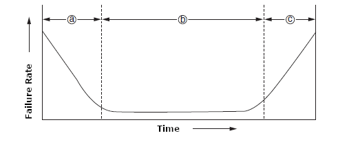
(a) As we can see, right after manufacture and start of use, capacitors go through a period in which the number of failures is more significant, usually due to failures in the manufacturing process or incompatibility of operation. Most manufacturers eliminate problems from this phase by testing them for some time before shipping.
(b) This is the normal operating phase in which capacitors have the lowest failure rate and is usually specified in the data sheets as determining their durability (lifetime).
(c) At the end of its useful life, we increase the failure rate, indicating that the component no longer fulfils its functions.
Faults have different natures, such as short-circuiting, opening, loss of capacitance, increase in leakage current, leakage of electrolyte.
Several factors will influence the lifetime of an electrolytic capacitor.
Effect of stress on durability
The first effect that must be analyzed is how the voltage applied to an electrolytic capacitor influences its useful life.
According to studies, if we use an electrolytic capacitor in a circuit with a lower voltage than specified, it will not last long. According to these studies, the variations in the failure rate are too small to be considered.
Effect of loading and unloading on service life
When an electrolytic capacitor is discharged and charged, chemical processes in the electrolyte can influence its service life. One of the effects is the current created in the process that can generate heat, reducing capacitance and service life.
Peak current
For example, in a power supply or a switching circuit, the initial current when voltage is applied, and the capacitor is fully charged can be very intense. If this current lasts very little, the heat generated in this process will not affect the component, but if it is a repetitive process, it can affect the capacitor's durability.
Overvoltage
Applying a voltage higher than specified can cause reactions to occur in forming more dielectric at the anode with increasing leakage current.
If this reaction increases with the action of voltage, the temperature rises with the formation of gases. With these gases, the pressure can increase to the point of destroying the component.
Influence of the environment
The presence of ions in the environment can affect electrolytic capacitors. These components are susceptible to chlorine and bromine ions. Of course, the capacity of sealants comes into play.
The penetration of these contaminants affects the electrical properties of capacitors, which can lead to failures.
A precaution must be taken when cleaning, which should only reach the printed circuit board and not the components. Several substances should not be used when cleaning boards that contain these components. Manufacturers' datasheets should be consulted.
Storage
That is perhaps the biggest problem with electrolytic capacitors when isolated or already part of the equipment. The most significant number of queries we received is precisely related to this topic.
Because they use an electrolyte directly involved in their functioning, electrolytic capacitors depend on temperature and time, as these electrolytes lose their chemical properties.
In storage, electrolytic capacitors can deteriorate for two reasons: evaporation of the electrolyte or dissolution of the dielectric.
According to the manufacturers, a capacitor stored for an extended period that makes them lose their properties can be subjected to a voltage treatment process (Electrolytic Capacitors Restorer (ART584E)).
A typical restoration technique connects a 470 ohm to 100 k ohm resistor in series with a capacitor and applies the rated voltage for 30 minutes to 4 hours. At each period, the capacitor is measured, paying attention to its leakage. The procedure varies by manufacturer.
Today's capacitor manufacturers can obtain components with excellent durability, but we must always consider recovering or storing old equipment. Current manufacturers even guarantee a lifetime of more than 15 years for their components.
In Figure 9, we have a degradation curve for an electrolytic capacitor after one year of storage at two temperatures.
In storage, we expect an increase in leakage current that depends on the component voltage value. The greater the capacitor voltage, the greater the increase in leakage current with storage time.
A major manufacturer of electrolytic capacitors recommends that once stored (not in use):
- Test it after three years before checking whether it can be reset to achieve the specified leakage current.
- After four years, it may be necessary to go through a restoration process.
- After five years, it will undoubtedly need to go through a restoration process.
- After ten years, it will be at the end of its useful life and should not be used.
For equipment that must be stored for an extended period, some procedures are controversial, as they vary according to the information source.
Thus, it is recommended that periodically the equipment is put into operation so that the electrolytic capacitors, when receiving power, automatically go through the restoration process.
For some, the equipment must be restarted at intervals that vary between three months to one year. However, analyzing the deterioration curves for electrolytic capacitors, we see that the ideal time should not exceed one year. And, the equipment must remain on for at least 4 hours, for 1 to 3 cycles.
Remember, store in a cool, dry place. Use silica gel if necessary and avoid contaminants such as cleaning substances stored in the same place, releasing chlorine and bromine ions.
Eventually, if any capacitors have problems in this process and can be identified, they can be removed from the circuit and taken to an independent restoration process.
Documentation consulted from companies
TDK, Panasonic, DfR, Nippon Chemi-Com. Cornell Dublier


