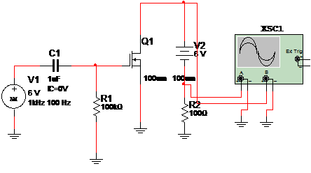
The circuit in figure 1 is a dynamic test for FETs. The characteristic of a FET is displayed in the virtual oscilloscope of the Multisim. The signal source is a 6 V x 100Hz signal applied to the gate of the transistor under test.

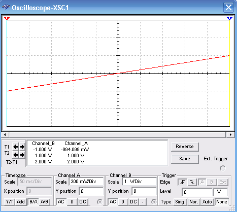
The wave shape is displayed as shows figure 2. Observe the adjustments of the virtual oscilloscope. The sweep is adjusted for the A/B mode.

To download the simulation files and Netlist - click here (msb0065.zip)


