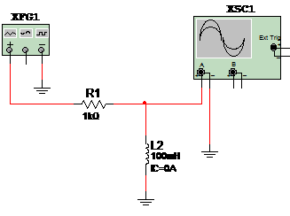
This circuit is used to test an inductor (coil) allowing the observation of its opration in an R-L Circuit. The signal source is adjusted to produce a 1 kHz 2 to 10 V sqare signal (50%). The indictor must vave indurtances in the range between 1 mH to 1 H. The circuit for simulation is shoen in figure 1.

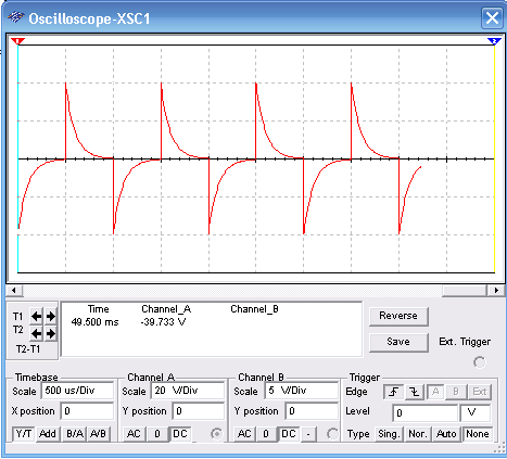
Figure 2 shows the wave shape of the signal observed in the circtual oscilloscope of the MultiSIM.

Download the simulation files and Netlist - click here (msb0071.zip)


