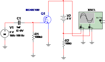
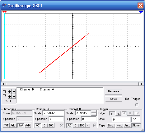
This simulation shows how to test an IGBTs using a signal source and the virtual oscilloscope of the MultiSIM. A 1 kHz x 6 V modulated in 100 Hz signal is applied to the IGBTs biased with a 6 V source as shown. The wave shape for a good IGBT is displayed in the virtual oscilloscope. Figure 1 shows the circuit.

Figure 2 shows the wave shape for a good IGBTs. Observe that the oscilloscope is adjuste for the A/B time base.

Download the simulation files and Netlist - click here (msb0078.zip)


