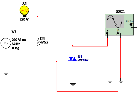
This circuit is used to test a triac and also to teach how it works. The load is an incandescent lamp and the signal source is the AC power line. The wave shape in the circuit is displayed by the virtual oscilloscope of the MultiSIM. This circuit only acts as solid state switch, not a dimmer. Figure 1 shows the circuit.

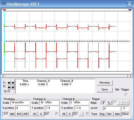
The wave shapes in the circuit are given in figure 2. Observe the adjustments for the oscilloscope virtual of the MultiSIM.

Download the simulation files and Netlist - click here (msb0080.zip)


