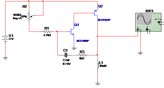
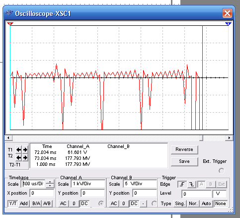
The circuit shown by the figure below can produce signals in the range between 20 kHz and 30 kHz. Power supply can range from 6 to 9 V… If you replace Q2 at a BD136, power voltage can be increased to 12 V. R2 adjusts the frequency; The wave shap displayed by the oscilloscope doesn’t correspond to the real due the algorithm in the MultiSIM. This displays only is used to see that the circuit oscillates.


To download the simulation files and Netlist - click here (msb0122.zip)


