This circuit can be used to recognize a tone by its frequency.
When this tone is present in a circuit the relay is energized, which could supply power to a selected appliance.
Wired to the output of a receiver, the circuit can be used as part of a tone modulated wireless remote control.
The receiver can be a common FM radio or an infrared receiver, depending on the intended application.
The circuit can be used with tones ranging up to 100,000 Hz. The circuit is tuned by P1.
Inputs of other units can be wired in parallel to get a multi-channel remote control system.
Take care to avoid using harmonic frequencies.
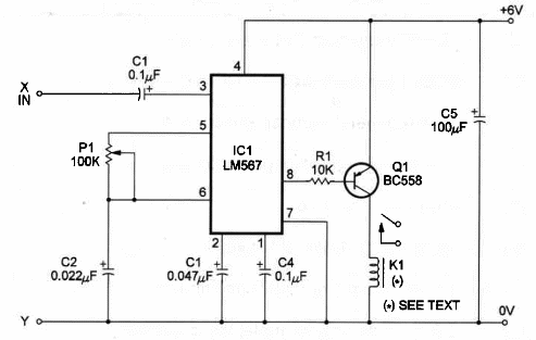
The schematic diagram of the Tone Activated Relay is shown in Figure 1.

The heart of the circuit is the LM567 IC, a National Semiconductor PLL (Phase-Locked Loop) that drives the relay through transistor Q1.
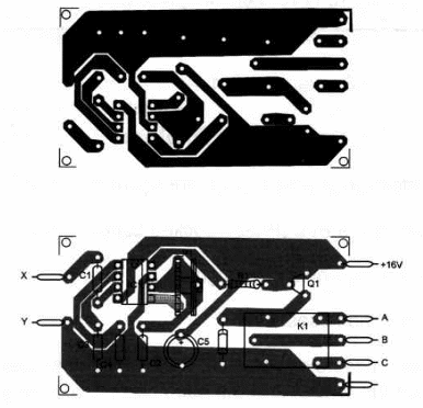
Components placement on a homemade printed-circuit board is shown in figure 2.

Placement is not critical, but when operating in frequencies above 50,000 Hz it is important to avoid long connections.
The relay is any type with a 6V coil and current rated for values between 10 and 100 mA.
Position of the polarized components, such as the diode and electrolytic capacitor, should be observed.
To use:
Wire the output of an audio generator or audio oscillator to points X and Y.
The signal should have amplitude in a range between 100 mV and 1 V peak-to-peak for best results.
Adjust P1 to trigger the relay. Reduce the signal amplitude and trim P1 for the best performance.
Tone-Activated Relay
lC1 - LM567 Integrated Circuit (National)
Q1 - 80558 general-purpose PNP silicon transistor
D1 - 1N914 general-purpose silicon diode
P1 - 100,000 ohm trimmer potentiometer
K1 - relay - 6V - see text
R1 - 10,000 ohm, ¼ W, 5% resistor
C1, 4 - 0.1 µF ceramic or metal film capacitor
C2 - 0.022 µF ceramic or metal film capacitor
C3 - 0.047 ceramic or metal film capacitor
C5 - 100 µF, 12 WVDC electrolytic capacitor
Ideas to Explore
To get better performance or to learn more about the circuit:
Explain how a PLL (Phase-Locked Loop) works.
What are harmonics of a signal?
Science and uncommon uses:
Remote sensors can be used to close the relay. Using an oscillator to produce the tone, the wires used can be very long, reaching distances up to 5 miles.
You can use a small oscillator as transmitter and this circuit as part of a receiver to activate devices by telephone line.
Connect the input of this circuit to the output of an audio amplifier. Plug a microphone to the input of the amplifier. VWth some practice you can control the relay by whistling.
You can also use this tone-activated relay to control appliances from your computer, using the multimedia audio output. Write a program to produce a tone when an icon on your Windows screen is clicked with the mouse.
The tone can be used to turn on the relay if the circuit is plugged to the audio output of your computer. Three modes of operation are possible:
a) By adjusting the length of the tone pulse you can turn on any appliance connected to the relay during this time interval. The appliance will turn off after the pulse ends.
b) Using a monostable with a 555 timer, for instance, a short pulse can turn on the appliance after a preadjusted time interval.
c) Using the turn-on-and-off circuit, described in this section, you’ll have a bistable operation: a click on the icon' turns on the appliance controlled by the relay, and the next click turns it off.


