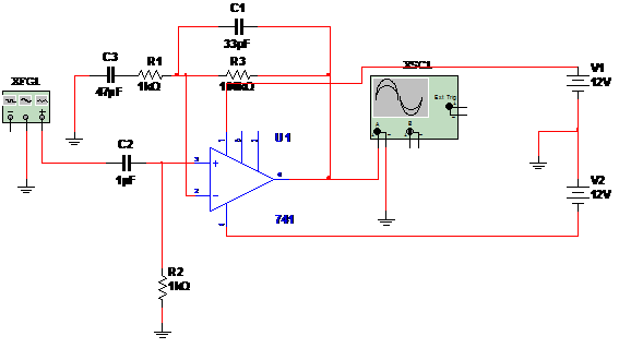
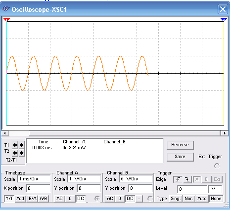
In the circuit shown by figure 1, a10 mV AC signal applied to the input produces a 1 V signal in the output. The sine signal is amplified by the 741 and gain is given by R3. The output has a low impedance characterstic and input is presents a high impedance. Equivalent to the 741 can be used. Power supply is dual with voltages ranging from 6 to 12V. See the adjustments for the function generator and oscilloscope for correct display of the wave shape.


To download the simulation files and Netlist - click here (msb0038.zip)


