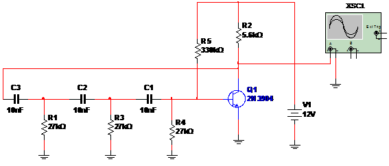
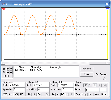
In this oscillator a phase shift network formed by C1, C2, C3 and R1, R3, R4 determine the fase rotation of the feed back signal and also the frequency. Values for the capacitors and resistors can be calculated by explanations given in the section Mathematics for Electronics in this site. Other transistor can be used such as the 2N2222, BC548, etc. For supply can be made from sources between 9 and 12 V. Current drain is very low. Bellow the simulation in the MultiSIM Blue. Atempt to the oscilloscope adjustments.


To download the simulation files and Netlist - click here (msb0039.zip)


