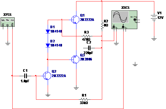
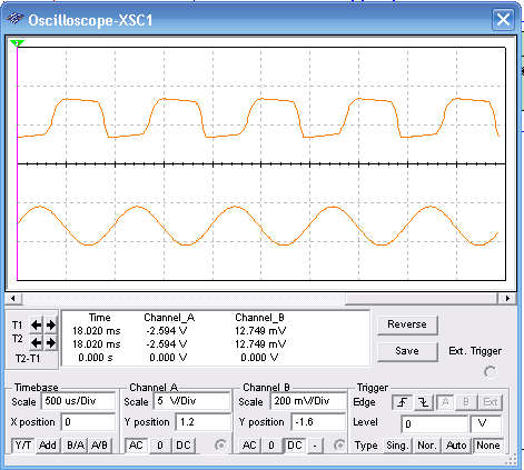
This audio amplifier uses 3 transistor in a traditional configuration named complementary output. Each transistor amplifies half cycle of the input signal, applying it to a 8 ohm load (loudspeaker, for instance). The amplifier source about 500 mW when powered from a 12 V power supply. General purpose NPN and PNP transistor can be used in this circuit. In the simulation using the MultiSIM BLUE, a 100 mV x 1 kHz signal is used. Seed the function generator and Oscilloscope adjustments for correct simulation.


To download the simulation files and Netlist - click here (msb0028.zip)


