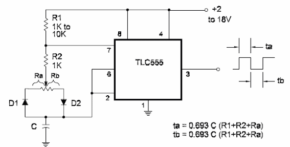
The time the output is high (1) of a TLCSSB in the astable configuration depends on Ra and C. The time the output remains low (0) depends on Ra, Rb, and C. It is easy to see that it is impossible to have duty cycles lower than 50 percent using this basic configuration. The circuit shown here is a variable-duty cycle oscillator that uses the TLC555 (and is also valid for the bipolar 555). The formulas to determine the frequency and duty cycle are given in the diagram. The diodes are general-purpose types, such as the 1N914 or 1N4148.


