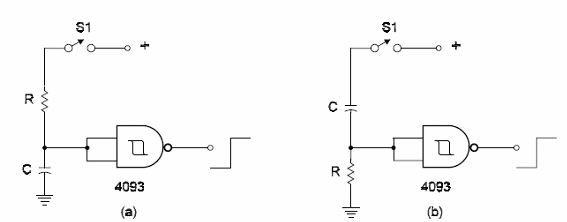
Simple timers can be designed using inverters or any other gate that can be connected as inverter. Figure bellow shows how the gates of a 4093 can be used in two types of timers. In [a], when S1 is closed the output of the IC goes to “1" during a time interval determined by R1 and C1. After this interval the output goes to In [b], the output goes to “0" when the switch is closed and after the time interval determined by R1/C1 goes to R1 can be in the range between 10 k ohm and 22 M ohm. The minimum value for C1 is 100 pF. These timers can provide time delays up to 30 minutes depending on the value of the components used.


