In its first version this article was written in Portuguese for a Brazilian magazine and translated to English to be part of my book Electronic Projects from the Next Dimension (Newnes – 2001). So, the project is intended to researches in paranormal voice phenomenon (transcommunication). See more in the site.
Perfect sound reproduction cannot come from a tape, loudspeaker, or earphones.
The output power is low, and the quality of the device (earphone or loudspeaker) may not be high enough to make it easy to find the voices.
Separating the voices from the noise isn’t a simple task, and it requires much concentration and patience. However, you can increase the performance of your circuit when reproducing the tapes by adding an audio output filter.
The first circuit of an audio filter shown here is very simple and uses only four components. But the main attraction in this project is that it doesn’t need any power supply, because it is a passive filter.
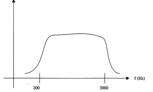
As the human voice has a frequency spectrum concentrated in the medium frequency band as shown in Fig. 1, when trying to detect the voices, the best results are obtained when high and low frequencies are cut off.

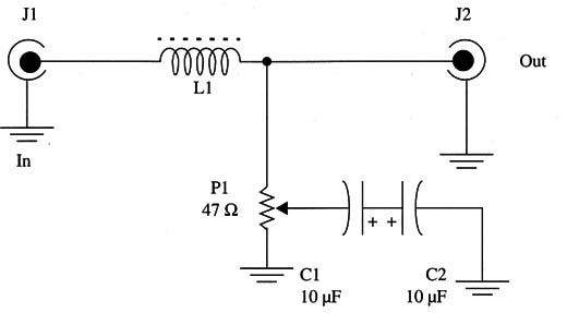
The passive filter circuit shown in Fig. 2 is plugged between the output of a tape recorder and the earphone or the input of an amplifier (such as those shown for earlier projects).

It is a bandpass filter, which is a circuit that lets signals pass within a specified frequency range but cuts them off above and below.
The low-frequency signals are cut by an amount determined by the adjustment of P1, and the high-frequency components of the signal are cut according to the value of L1. By adjusting the circuit, you can let pass only the frequencies where the voice signals are concentrated, making it easier to find them.
L1 is formed by 200 to 500 turns of wire, between 28 and 32 AWG, in a ferrite rod of 5 to 10 cm length (any diameter between 0.8 and 1.2 cm is suitable).
All the components can be housed in a small plastic box. To plug the circuit into the output of the tape recorder (monitor), use an appropriate plug and a shielded cable with a length up to 50 cm. To plug a headphone into the circuit, use a jack appropriate for the headphone plug. If you intend to plug it into the in- put of an amplifier, use a shielded cable with appropriate plugs.
The correct use of this circuit is between the output of the amplifier or tape recorder and a low-impedance transducer such as a loudspeaker or an earphone.
When installing the filter between a low-impedance source and a high-impedance device such as an amplifier, distortion due to impedance mismatch can occur. In this case, wire a 100 ohm X 1 W resistor in parallel with the filter’s output.
Using the Circuit
Plug the filter into the output of the tape recorder and let the machine record in the location where you intend to find the voices. Plug the earphone into the output of the filter. Note that this circuit is designed to be compatible with the tape recorder and is designed for low-impedance earphones of 8 to 100 ohm. If you’re using an audio amplifier, plug the output of the filter into the AUX (auxiliary) input of the amplifier.
Set the tape to run and adjust the filter control, trying different positions while looking for the voices. If you are using an audio amplifier, adjust its volume to obtain the best results.
Suggestions
The number of turns of L1 can be altered to change the filter performance.
Make such experiments, or use different filters (with different coils).
Capacitors C1 and C2 determine the high-frequency cutoff. Change them, experimenting with values between 1 and 100 µF.
L1 Coil (see text)
C1/C2 - 10 µF/ 16 WVdc, electrolytic capacitors
P1 - 47 ohm, Wire wound potentiometer
J 1, J2 - Input and output jacks or plugs according to the tape recorder, earphones, and amplifier (see text)
Ferrite rod, plastic box, knob for P1, Wires, solder, etc.


