This circuit can be used as power supply for many of the projects described in this site. In fact, to perform experiments in electricity the reed needs a source of voltage. Batteries are source of voltage but as battery gets old, an experiment or circuit may fail because the battery can no longer supply the need voltage. Instead of using a battery the reader can use a power supply that is a circuit that converts the AC voltages from the AC power line in DC low voltages as need by circuits and experiments.
This small power supply described here can supply currents up to 500 mA to small DC motors, incandescent lamps and electronic circuits with no need of regulated voltages and that work with voltages in the range between 6 and 9 volt.
The circuit uses a PI filter to minimize hum when supplying audio circuits and is isolated from the AC power line as it uses a transformer. This means secure operation in any condition avoiding dangerous shock hazards.
How it works:
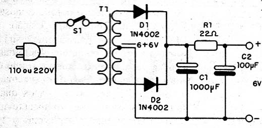
The transformer source the low AC voltage to a full wave rectifier arranjement with two silicon diodes. After the diodes we will find not DC voltages because they consist in pulses.
To get a pure DC voltages after the diodes we use a PI filter consisting in the components C1, C2 and R1.
Using the power supply:
Wire the load to the output of the power supply. Remember that in a non-regulated power supply, when the output is open (no load) the voltage is about 1.4 times greater than the secundary voltage for which the transformer is rated. This voltage will fall when a load is powered on, according its current drain.
Figure 1 shows the schematic diagram of the Mini Power-Supply.

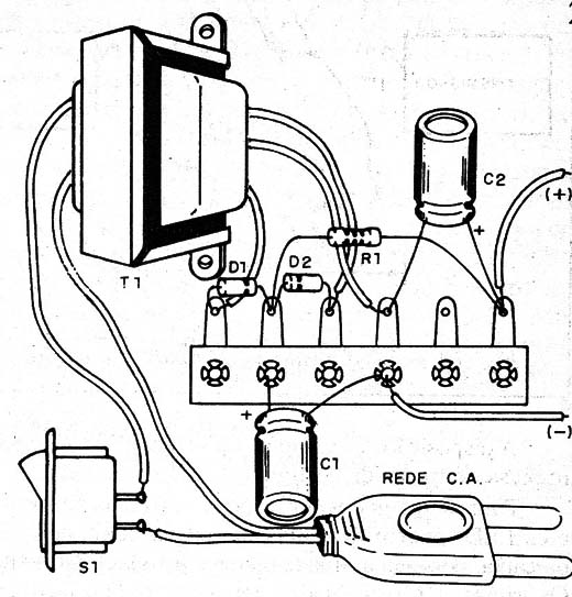
The components are mounted as shown in figure 2.

All the components can be housed into a wooden or plastic box.
Conections to the external loads can be made using wires with alligator clips or terminals. Use a red alligator/terminal to the positive pole and black to the negative.
Positions of the polarized components as the diodes and electrolytic capacitors should be observed.
The transformer is not a critical piece in this project. Any small transformer rated to currents between 200 and 500 mA should be used. But, you should remember that the maximum current available in the output to power the loads is the current rated to the used transformer.
Using the Power Supply:
Wire the load to the output. Observe position of the alligator clips according the poles.
D1, D2 - 1N4004 or equivalent - silicon rectifier diodes
T1 - Transformer: 117 VAC x 6 V + CT x 500 mA
S1 - SPST - Toggle or slide switch
R1 - 22 ohm, 2 watt, 5% - resistor
C1 - 1,000 µF/ 12 WVDC - electrolytic capacitor
C2 - 100 µF/ 12 WVDC - electrolytic capacitor


