Direct amplification AM experimental radios are very interesting projects for beginners because they use only few components and don't need special instruments to make adjustments.
Here we describe a receiver which uses only two transistor as active elements and can tune local strong AM stations using as antenna only a piece of wire.
The antenna should be a common insulated wire 6 to 10 feet long placed on the floor or high in the walls.
Signal amplification is made by two complementary transistors with an output power high enough to drive a small loudspeaker.
The radio can be powered from two or four AA-cells or, if you prefer, from a power-supply plugged to the AC power line.
Since the circuit is not selective and sensitive as a commercial radio it is recommended only as an experimental project to demonstrations or to learn how to make electronics projects and how radio receivers work.
How it works:
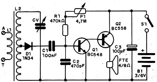
L2 and CV forms the ressonant circuit that determines the frequency of the station to be received.
The signal in the output of the ressonant circuit is detected by D1 and the audio signal that results in this process is applied, via C1, to the base of Q1.
C2 offer a path to ground to the high frquency component of the detected signal.
Q1 and Q2 are wired as a directed coupled amplifier with the polarization for better performance adjusted by P1.
L1 is formed by 20 + 80 turns of 26 to 30 AWG wire on a ferrite rod. L1 is formed bu 5 turns of the same wire on the same ferrite rod. Any ferrite rod with lenghts between 4 and 12 inches can be used. You can find a ferrite rod suitable for this project in any old non-functioning transistor radio.
An interesting point to observe is that the radio selectivity and sensivity is determined by the position of the coil tap. Displacing the tap from the original position to other near the ground end the selectivity increases and sensibility decreases. In the other hand, moving the tap towards the antenna end the selectivity decreases and sensivity increases. Make experiments changing the tap position as suggested in Ideas to Explore.
CV is any variable capacitor with capacitances ranging from 150 to 400 pF. You can also find this capacitor and the ferrite rod in any non-functioning old transistor radio.
D1 is any germanium diode. You can also use any general purpose PNP germanium transistor as diode wiring the base as catode and the emitter as anode. Ignore the colletor lead.
Figure 1 shows the complete schematic diagram of the two-transistor radio.

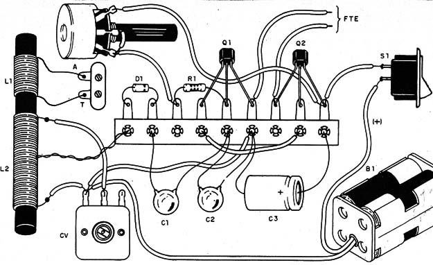
The components are soldered on a terminal strip used as chassi as shown in figure 2.

The terminal strip is fixed by screws on a wood or plastic base with the cell holder, loudspeaker, CV and P1. Use a metal plate bend to form an "L" to fix the loudspeaker, CV and P1.
Antenna and ground can be plugged to the circuit using a terminal strip with screws or two pieces of wire with alligator clips.
To get better performance a good ground connection is very important. See our project in this book "Matchbox radio" to more details about how to make a good ground connection.
To use the radio: turn on S1 and adjust P1 and CV to get the better signal from a selected station.
If the listening strenght is not enough to drive the loudspeaker you can replace it by a low impedance earphone.
Q1 - BC548 - general purpose NPN silicon transistor
Q2 - BC558 - general purpose PNP silicon transistor
D1 - 1N34 - any germanium diode - see text
L1, L2 - Coil - see text
CV - 120 to 400 pF - variable capacitor - see text
R1 - 470,000 Ω, 1/4-watt, 5% - resistor
P1 - 4,700,000 Ω - potentiometer
C1 - 0.1 µF - ceramic capacitor
C2 - 470 pF - ceramic capacitor
C3 - 100 µF/12 WVDC - electrolytic capacitor
S1 - SPST - toggle or slide switch
B1 - 3 or 6 V - 2 our 4 AA-cells
SPKR - 4 or 8 Ω - small loudspeaker (2 or 4 inches)


