During the Second World War germans and japaneses developed some communications devices using light beams. These devices were basically mechanical modulated systems using a mirror placed on a membrane. Sound vibrations falling on the membrane changed the light beam of a light source and that could be detected by a remote receiver.
The light source was not critical as any incandescent lamp could be used and the optical system included lens, prisms and parabolic mirrors to produce a parallel output beam with long range capabilities.
Tests made by the U.S. Army with one of these devices, used by germans, named Lightsprecher 250/130, manufactured by the well known Carl Zeiss optical firm, revealed a voice transmission range of about 8,5 miles or 13,7 kilometers.
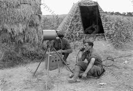
We don't think that our simple light beam telegraph goes so far using common light sources used as transmitter but certainly over good weather conditions (without fog or pollution) and with the aid of optical systems it can range some hundred feet or even some miles in open field.
And we also have to say that our communication uses telegraph codes or Morse Code as it can't transmit sounds. It is a telegraph and not a telephone or interphone.
But the reader with abilities in electronics and optics can easily increase the capabilities of this project. For these readers we suggest a brief look at the book "Light-Beam Communications" by Forest M. Mimis, III.
The basic idea adopted by this project is to place the LDR (used as sensor) in a favorable point to detect the incoming light beam.
Using an electric torch or other light source as a incandescent lamp or a laser pointer it is possible to key a coded message to this receiver.
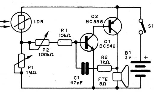
The electronic part of the project, described here, is the receiver. The receiver is a light triggered oscillator converting light pulses on the sensor in tone pulses reproduced by a loudspeaker.
The circuit is portable and as it is powered from AA cells it can be used in open field experimental communications systems or scientific experiments.
You also can use it to secret contacts with your neighbors, accross the street or in other places, without the need of wires or any other phisical media to transport the signals.
Other applications involving scientific experiments can be found in the item "Ideas to Explore" at the end of this article.
The schematic diagram of the Light Beam Communication is shown in figure 1.
The components are soldered on a terminal strip in the basic mounting as shown in figure 2.
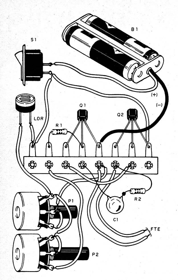
You can house the circuit into a small plastic box with the LDR and the two potentiometers mounted in the front panel.
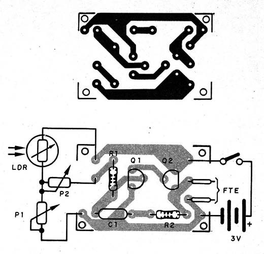
You also can make the circuit using a PCB as shown in figure 3.
The LDR can be placed far from the circuit using common wires to this connection. The wires can be placed as far as 100 feet from the circuit without any problem.
To get directivity to the receiver, the LDR should be mounted at the focus of a convergent lens inside an cardboard opaque tube. Mounting it into a tube you also will avoid the influence of the ambient light and will increase sensivity. Figure 4 shows the circuit as a portable unit.
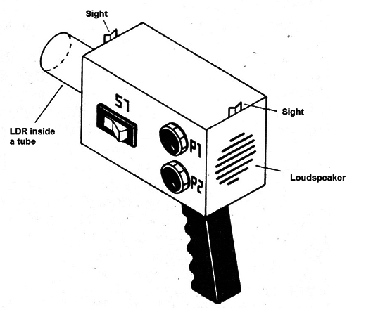
The loudspeaker can be found in any non-funtioning portable radio or record. You can also replace the loudspeaker by a low impedance earphone without the need of any modification in the original project.
Using the light beam-telegraph:
Adjust P1 and P2 to have no sounds at the loudspeaker. Avoid ambient light to fall onto the LDR to get better sensivity. Dark opperation will give a very long range capability to the circuit.
Produce light pulses with an electric torch or other light source and adjust now P2 to get the desired tone pitch to the pulses reproduced by the loudspeaker.
Use the Morse Code to make communications. Two units as this form a bilateral light-beam communication system.
Q1 - BC548 - general purpose NPN silicon transistor
Q2 - BC558 - general purpose PNP silicon transistor
LDR - Common Photo Resistor or LDR
R1 - 10,000 ohm, 1/4-watt, 5% - resistor
R2 - 1,000 ohm, 1/4-watt, 5% - resistor
P1 - 1,000,000 ohm - potentiometer
P2 - 100,000 ohm - potentiometer
C1 - 0.047 µF - ceramic or metal film capacitor
SPKR - 8 ohm - small loudspeaker
S1 - SPST - toggle or slide switch
B1 - 6 V - 4 AA cells


