Fluorescent lamps are faster than incandescent lamps, so they are better for producing fast flashes in a stroboscopic circuit.
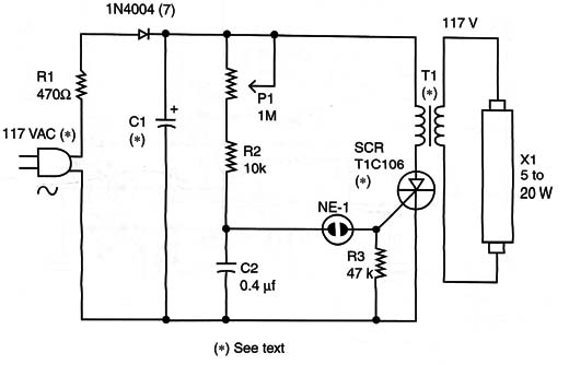
The circuit shown in Figure 1 is not powerful, but it can be used in some experiments involving bionics such as animal conditioning, working with stress, and others (*).

(*) This project was originally included in my book Bionics for the Evil Genius (TAB – 2006)
The circuit consists of a relaxation oscillator using a neon lamp to trigger a silicon-controlled rectificar (SCR).
The capacitor C1 charges through R1 and D1 until the voltage across the lamp rises enough to trigger the light. At this moment, the neon lamp lights up, and the capacitor C2 is discharged through the gate of the SCR. The result is that the SCR conducts the discharge current of C1, which flows across the low-voltage Winding of the transformer.
The high-voltage pulse produced at the secondary is also applied to the lamp that flashes for a moment.
The pulse rate can be controlled by P1, and the power of the flash depends on the capacitor C1.
The transformer can be any type used in power supplies with a primary rated to 117 VAC and a secondary of 9 to 12 volts and currents ranging between 250 and 600 milliamps.
Additionally, any 5- to 20-watt fluorescent lamp can be used. Even ones that do not function anymore because they are weak will glow using this circuit. The high-voltage pulses can easily be higher than 117 VAC, triggering the lamp on.
Depending on the components, to compensate tolerances C2 can be changed. Values that range from 0.1 to 0.47 µF can be tested.
To operate from the 220/240 VAC power line, change R1 to 1k ohm, replace D1 with a 1N4007, and use the TIC106D for the SCR.
It is not necessary to mount the SCR on a heatsink because it functions at short time intervals without generating large amounts of heat.
SCR: TIC106B (117 VAC power line) or TIC106D (220/240)
D1: 1N4004 (117 VAC) or 1N4007 (220/240 VAC) silicon rectifier diode
NE-1: NE-2H or equivalent neon lamp
R1: 470 ohm x 10 W (117 VAC) or 1 k!) x 10 W (220/240 VAC) wire-wound resistor
R2: 10 k ohm) x 1/8 W resistor, brown, black, orange
R3: 47 k ohm x 1/8 W resistor, yellow, violet, orange
P1: 1 M ohm,lin or log potentiometer
C1: 4.7 to 22 µF x 200 V (117 VAC) or 400 V (220/240 V) electrolytic capacitor
C2: 0.1 µF x 100 V or more polyester capacitor
T1: Transformer (see text)
X1: 5 to 20 W fluorescent lamp
Other: PCB, wires, solder, power cord, etc..


