AC-powered appliances, such as lamps, small home appliances, tools and other items, can be controlled by your fingertips using this circuit. Also, test equipment and experiments can be controlled by this circuit.
You can turn on any load by first touching time sensor X1, then turn it off by touching X1 again.
There is no shock hazard, as the control circuit is completely isolated from the AC power line.
The control circuit is powered from four or eight AA cells, or, if you prefer, a power supply ranging from 6 to 12 volts according to the relay coil.
Don’t use transformerless power supplies because they are not isolated from the AC power line and can cause severe shocks and shorts.
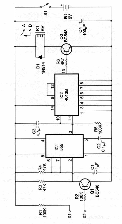
The schematic diagram of the Touch On/Touch Off Relay is given in Figure 1.

The circuit uses two le. The 555 timer works as a monostable, producing one control pulse when the sensor is touched. The 4013 is a flip-flop that controls the relay by a transistor.
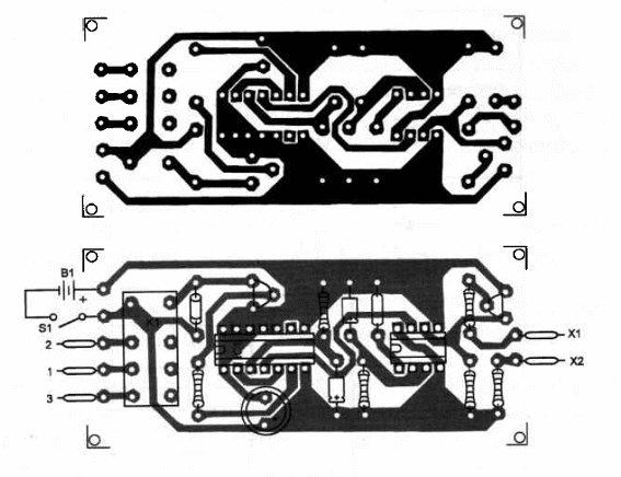
Components placement on a homemade printed-circuit board is as shown in Figure 2.

Component layout should be altered if the relay used in the project is an equivalent of the type indicated in parts list.
Relay coil voltage is determined by the power supply voltage and the load current requirement.
You can use a mini 1A DPDT (Radio Shack 275-249) 12V, 280 ohm, 43 mA, and wire it as shown in the figure, or use another type of relay, depending on the load requirements.
A 1A SPDT mini-relay (Radio Shack 275-278) is suitable for heavy duty appliances.
As a simple rule, you can use a 6- or 12-volt relay with coil currents ranging from 10 to 100 mA and contacts up to 1oA, according to the task you have in mind.
Positions of the polarized components, such as the diode, electrolytic capacitors and transistor, should be observed.
Sensors are the same as the ‘Touch Switch” project described in this section (MIN021E).
Don’t use metallic box to house the device, as there are parts connected directly to the AC power line. Be sure that there are no power line contacts with the low voltage circuit to avoid shocks and dangerous shorts.
You can also use the normally closed contacts to turn off a load when the relay coil is energized.
Remember that current requirements are high when the relay coil is energized and low when the transistor 02 is off (relay coil nonenergized).
That is an important factor to consider if you are using batteries to power the unit.
After you are sure that you have wired all parts of the circuit correctly, plug the power cord into the wall socket.
You can now test the circuit.
Connect a load to the output (relay contacts) and touch the sensor.
The load should be powered ON if all is OK.
Touch On-Off Relay
lC1 - 555 integrated circuit - timer
lC2 - 4013B CMOS integrated circuit - dual flip-flop
01, 2 - BC548 General-purpose NPN silicon transistors
D1 - 1N914 General-purpose silicon diode
K1 - Relay - see text
R1, 2, 5 - 100,000 ohm, 1/4W, 5% resistors
R3, 4 - 47,000 ohm, ¼ W, 5% resistors
R6 - 1,000 ohm, ¼ W, 5% resistor
C1 - 1 µF, 25 WVDC electrolytic capacitor
02 - 0.1 µF ceramic or metal film capacitor
C3 - 4.7 µF, 12 WVDC electrolytic capacitor
C4 - 100 µF, 16 WVDC electrolytic capacitor
S1 - SPST toggle or slide switch
B1 - 6 or 12 V (according to relay) - see text
X1, 2 - sensor - see text
Ideas to Explore
To learn more about the circuit or to get better performance:
Better performance can be obtained by replacing Q1 with a Darlington transistor, such as a BC517.
A 100,000 ohm potentiometer placed between the base of Q1 and the negative pole of the power supply will give a sensitivity adjustment for the circuit.
Explain how a flip-flop, as used in this circuit, works, and the function of the C3/R5 network in this project. Explain why the current flowing through the fingers when the sensor is touched doesn’t cause any shock hazard.
Depending upon the application, you can power ON the load when relay is not energized (to reduce power consumption). That is possible using the normally closed contacts of the relay.
Science projects and uncommon uses:
By connecting a reed switch between points X1 and X2 you can use the circuit to detect movement of mechanical items in experiments or projects. Just affix a magnet on the moving item to act on the switch.
Experiments with animals can be conducted with this circuit by using appropriate transducers connected between X1 and X2.
An LDR can be used to control the circuit with a flash of light. A lantern, cigarette lighter, etc., can be used to turn appliances on or off.


