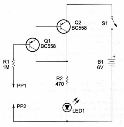
This circuit can be used to test electronic components such as diodes, resistors, coils, transformers, lamps, fuses, switches, loudspeakers and many others.
The state of the component under test is indicated by an LED.
When the probes are separated or when the resistance between them is very high (more than 1,000,000 Ω) the LED is off.
When the resistance is low (the transistor is in a conduction state) the LED is on.
The circuit is powered from a 6- or 9-volt supply (AA cells or battery).
Current drain is less than 10 mA with the LED on. Ft2 value depends on the power supply voltage.
For a 9 V supply we recommend 820 or 1,000 Ω for R2.
A schematic diagram of the Continuity Tester is given in Figure 1.

Two tran- sistor are wired as a Darlington pair.
The configuration reduces the current flow between probes to microampere values.
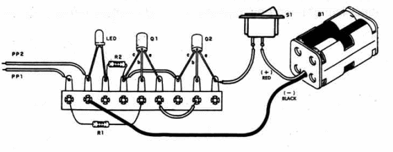
Components placement on a terminal strip, used as chassis, is shown in Figure 2.

It is very important to observe positions of the transistors and LED.
House the device in a small plastic box and use probes or alligator clips to connect the components under test.
Continuity Tester
Q1, 2 - BC558 general-purpose PNP silicon transistors
LED - Common red, green or yellow LED
R1 - 100,000 ohm, ¼ W, 5% resistor
R2 - 470 ohm, ¼ W, 5% resistor - see text
81 - SPST slide or toggle switch
B1 - 6V or 9V (four AA cells or battery)
PP1, 2 - Red and black probes
Ideas to Explore
To get better performance or to learn more about circuit and devices:
Invert power supply poles and LED position and use NPN transistors. Will the circuit operate as the original version? A transistor such as the BC548 can be used in this experiment. You can also replace the LED and R1 with a 6-volt x 50 mA small incandescent lamp.
Determine the highest resistance that can be connected between probes that causes the LED to illuminate.
Science projects:
Conductability of chemical substances can be detected or demonstrated with this circuit. Use two bare wires as probes.
By replacing the LED with a 0-200 µA microammeter you can use this circuit as a lie detector. Small changes in skin resistance can be detected in this way. Skin resistance alters with stress or by the strain caused by an interrogation session.
Experiments with plants can be conducted involving alteration in the resistance between electrodes placed on their leafs .An interesting study about this subject is found in the book, The Secret Life of Plants by Peter Tompkins and Christopher Bird. The authors associate electrical phenomena in plants to a rudimentary nervous system.


