As commercial ohmmeters are cheap and easy to find, anyone who wants a good instrument for his own use will not build one.
But you can build a simple ohmmeter to demonstrate how it works or study how the big ones are made.
The simple ohmmeter described here can easily be made from a milliammeter or microammeter, and can be used in experiments, demonstrations and many other applications.
Our ohmmeter is also a voltmeter. And since this ohmmeter can measure a Iarge range of voltages and resistances we can say that it is, in practice, a multimeter.
Voltages can be measured in the range between 0 and 12 volts (the range used to power almost all circuits in this book), and resistances between 0 and infinite.
If using a 200 µA microammeter, the sensitivity will be 5,000 Ω per voIt.
This value is typical of several commercial types of common multimeters.
But you can use any other ammeter with a fuIl-scale value ranging from 100 µA to 1 mA. Simply change R1 to achieve best performance.
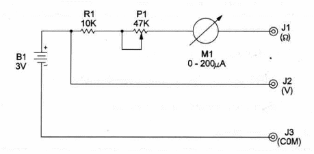
The schematic of the experimental ohmmeter is shown in Figure 1.

Note that we use only four components that can easily be housed in a small plastic box.
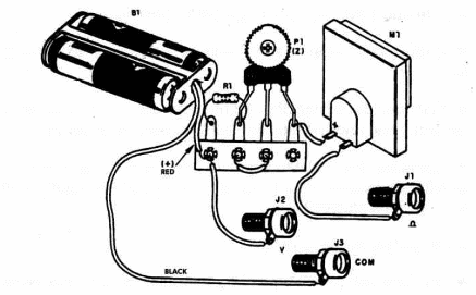
Layout is shown in Figure 2.

Components mounting is not criticaL and you can replace the banana jacks by probes or any other method to make external connections.
Probes are connected to the external banana jacks depending on the measurement you intend to make.
To measure voltage, the red probe is connected to J1 and the black probe is connected to J2.
To measure resistance, connect the red probe to J1 and the black probe to J3.
Put the probes together and adjust P1 to get an indication of zero at the instrument scale.
By using a series of known resistors, it is possible to calibrate the meter scale to read Ω directly.
Start from 0 (with J1 and J2 shorted), and note the meter readings when 1k, 2k, etc, resistors are connected across J1 and J3.
After calibrating the device to read Ω, use a variable power supply to calibrate the voltage scale.
Position of the polarized components, such as the ammeter and power supply (cells), must be observed.
Experimental Ohmmeter
B1 – 3 V - two AA cells
Fi1 - 10,000 ohm, ¼ W, 5% resistor
P1 - 47,000 ohm, ¼ W trimmer potentiometer
M1 - 0-200 µA microammeter - see text
J1 -3 - banana jacks
Ideas to Explore
To learn more about the circuit or to get better performance:
Explain how resistance and voltage scales operate in this ohmmeter.
Calibrate the scales of your ohmmeter using a variable power supply and some known-value resistors, as described above.
Calculate the resistance values read in the meter and compare with the real values of used resistors. Do your calculated results confirm previous studies?
Science and uncommon applications:
You can use the ohmmeter to determine sensor and media resistances in several experiments it you don’t have a commercial multimeter.
By wiring a 47,000 ohm potentiometer between J1 and J3 you can use this device as a position indicator. Cursor positions can be directly converted into current as indicated by the meter. A scale of angles can be arranged to read degrees directly.


