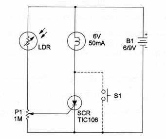
This circuit consists of a simple but effective light-activated alarm which uses only a half dozen components.
A light falling on the LDR turns on the SCR.
The lamp will remain on until the power is off or $1 is used to reset the circuit.
P1 adjusts sensitivity according to the application. To get better performance the LDR can be housed in an opaque tube with a convergent lens.
A 6-volt lamp can be used without problems since there is a voltage drop of about 2 volts when in the ON state.
The schematic diagram is shown in Figure 1.

S1 is optional, as you can reset the circuit by turning off the power supply.
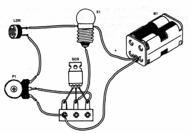
Components layout, using a terminal strip, is shown in Figure 2.

The lamp can be replaced by an LED in series with a 470 ohm resistor or a buzzer.
You also can control an audio oscillator, replacing the lamp with it.
The lamp isn’t a critical component. Any 6V lamp ranging from 50 to 250 mA can be used.
The LDR is a common CdS photoresistor. The SR1 needn’t be mounted on a heatsink as the current is very low.
Experimental Light-Alarm
SCR - TIC106 Silicon Controlled Rectifier
LDR - Common LDR - see text
P1 - 1,000,000 ohm potentiometer
X1 - 6V incandescent lamp - see text
B1 - 6-9V - four AA cells, D cells, battery or power supply
S1 - SPST momentary switch
Ideas to Explore
To learn more about the circuit or to get better perlormance:
Replace X1 with 3 6V relay to control external loads. Wire a 1N914 diode in parallel with the relay coil to prevent high-voltage kick from damaging the SCR.You can also control small audio oscillators or other devices.
Change position of the LDR with P1 to get a dark-activated alarm.
Explain how LDRs (Light Dependent Resistors) work.
Replace the LDR with a phototransistor. Will the circuit operate as you want?
Science projects:
This circuit can be used to monitor traps or events that involve object or animal movements.
Several LDRs can be wired in parallel to monitor more than one place at the same time. In a dark-activated alarm, when P1 switches position with the LDR, more than one LDR can also be used. But, in this case, you must wire the LDRs in series.


