You can use this simple metal detector to locate plumbing pipes, electrical wiring inside walls, find a lost watch or coin at the beach or even a treasure with gold coins buried years ago by pirates.
You can also use the circuit in experiments where you can show the magnetic properties of materials.
The differences between paramagnetic, diamagnetic, and nonmagnetic materials can be shown. Interesting experiments can be conducted using the metal detector described here.
This circuit will detect the presence of metallic objects through any nonconductive material such as dirt, wood, stone, plaster or plastic.
With a little practice, you will be able to detect metallic objects to depths of over several inches and will give you a fairly good idea of their size.
Our circuit uses the beat-frequency method to detect an object.
The frequency of the search coil oscillator changes when the conductance in the field of the search coil changes.
Therefore, when metals come within a short distance of the coil, the frequency is changed, which in turn changes the pitch of the audible sound.
The sound is produced by the speaker of a common AM receiver that tunes the coil oscillator.
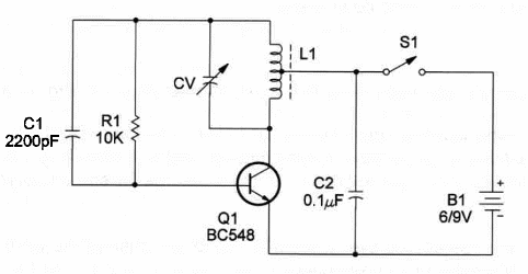
A schematic diagram'of the Metal Detector is shown in Figure 1.

Observe that the circuit is a very simple one-transistor oscillator.
You can also use a general-purpose PNP silicon transistor, inverting the power supply polarity.
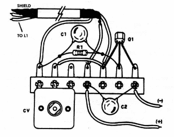
The physical arrangment of the electronic components, using a terminal strip as chassis, is shown in figure 2.

The critical part of this project is the search coil.
The search coil is wound in a large 6-inch plastic Frisbee. Begin by securing one end of the enameled magnet wire form (18 to 22 AWG) with masking tape.
On the tenth wrap (halfway) form a loop in the magnet wire for the center tap, then continue until you complete the 20 turns of wire.
It is very important to secure the coil wire firmly, as one loose loop in the coil will cause the detector to be unstable.
To use:
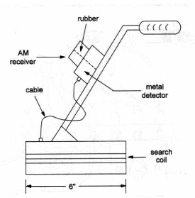
Fix a small portable radio close to the oscillator as shown in Figure 3.

Tune the radio to a free point of the range between 550 and 1,600 kHz. Adjust CV in the search coil oscillator to tune this signal as a whistle.
If you can’t find the oscillator signal in the AM band, reduce or enlarge the search coil by a few turns.
Passing the search coil over a metallic object will change the pitch of the whistle.
When the most pronounced change occurs, you should be directly over the metal object.
Metal Detector
Q1 - 30548 general-purpose NPN silicon transistor
L1 - Search coil - see text
CV - 365 pF - any variable capacitor (from nonworking AM radio)
C1 - 2,200 pF ceramic capacitor
C2 - 0.1 µF ceramic capacitor
R1 - 10,000 ohm, 1/4W, 5% resistor
S1 - SPST slide or toggle switch
B1 - 6 or 9V - four AA cells or 9V battery
Ideas to Explore
To get better performance or to learn more about the circuit:
Make experiments with different kinds of materials to see how the detector works with each one.
Explain what happens when a metal object is introduced in a magnetic field. Is there any way to identify the metal being detected?
The circuit can also be used as an RF’signal generator. To get the signal from this oscillator, connect a probe to the collector of the transistor with a 1,000 pF capacitor and an alligator clip to the emitter.
Science projects and uncommon applications:
Several experiments involving metal detection can be conducted using this simple metal detector. An example would be a work to show the differences between paramagnetic, diamagnetic and non-magnetic materials, as suggested earlier.
The search coil can be modified to apply RF signals to plants or animals. Experiments to find the effects of RF (Radio Frequency) on seed germination or plant growth can be made with this circuit.


