Acting on a capacitor charging, one oscillator (pins 1 , 2 and 3 of IC1) can modulate another oscillator in frequency, as described in this project.
The produced tones thus run from high to low and vice-versa at a rate determined by the first oscillator frequency and also by P1 and P2 adjustments.
The circuit can be used as a siren, part of alarms, games and many other applications.
With a 12V power supply the output power is up to a wattage representing an excellent audio level in a loudspeaker.
The basic circuit has tone, modulation rate and depth adjusted by trimmer potentiometer.
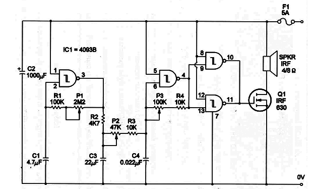
There are also some components that can be changed to alter the performance of the siren. C1, for instance, determines modulation rate and can range from 1 to 47 µF.
C2 determines modulation depth and rate and can also be altered within a large range of values. C3 determine tone frequency, ranging from 0.01 to 0.1 µF.
Power supply can range from 6 to 12 V. With a 12 V power supply current drain is as high as 2 or 3 amps. F1 is important to prevent problems with shorts.
Q1 is a power FET and equivalents can be used. You also can replace this transistor with a Darlington NPN power transistor such as TIP110, but you must also add a series resistor with base terminal.
Use a 10,000 ohm resistor for this task.
The schematic for the Frequency-Modulation Siren is shown in Figure 1.

Observe that two gates are used as oscillators and the other two of a 4093 IC are used as buffer-inverters.
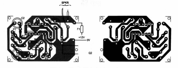
Components placement on a homemade printed-circuit board is shown in figure 2.

For experimental purposes the circuit can also be mounted on a solderless board, and it is important to place the transistor on a large heatsink.
Position of the polarized components, such as electrolytic capacitors, should be observed.
The speaker should be a high-power type for better performance. Installing it in an enclosure will provide better sound level.
Frequency-Modulation Siren
IC1 - 4093B CMOS Integrated Circuit
Q1 - IRF630 or equivalent Power FET
SPKR1 - 4 or 8 Ω, 4- to 8-inch speaker - see text
F1 - 5A fuse
R1 - 100,000 ohm, ¼ W, 5% resistor
R2 - 4,700 ohm, ¼ W, 5% resistor
R3, 4 - 10,000 ohm, 1/4W, 5% resistors
P1 - 2,200,000 ohm trimmer potentiometer
P2 - 47,000 ohm trimmer potentiometer
P3 - 100,000 ohm trimmer potentiometer
C1 - 4.7 UP, 16 WVDC eletrolytic capacitor
C2 - 1,000 µF, 16 WVDC electrolytic capacitor
C3 - 22 µF, 16 WVDC electrolytic capacitor
C4 - 0.022 µF ceramic or metal film capacitor
Ideas to Explore
To learn more about the circuit or to get better performance:
Explain how Power FETs work.
Alter C1, CZ and C3 to create new sounds.
Wire pins 1 and 5 together and to an external control circuit. The siren can be controlled by external logic circuits.
Determine the logic level in pins 10 and 11 when pins 1 and 5 go low. What will happen with current drain in this case?
Replace Q1 by a TIP31 or 30135 to operate with less power. The power supply should be reduced to 6 or 9V in this case.
Science projects and uncommon applications:
Replace R1 with an LDR and experiment with a light-controlled siren.
Use this siren as part of alarms.
Using this siren you can generate special sounds to experiment with animal conditioning.
Modulated ultrasounds can be produced by reducing C4 to values as low as 2,200 or 4,700 pF.


