When plugged to the output of any audio equipment with a power amplifier output (amplifier, radio receiver, etc), this device gives an indication of the sound level through a meter. The VU or ‘Volt Units’ meter is found in many audio amplifiers, like the professional types, to control the ‘balance’ between channels.
The meter is a micro-a-meter, rated to a full scale of 200 uA or close. If you are a lucky builder, you can find one in some non functioning equipment of your junkbox.
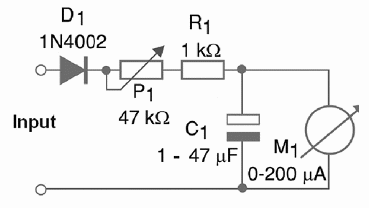
The circuit is plugged in parallel with the loudspeakers and you will need two (one for each channel) if you intend to use it in a stereo equipment. The only adjustment is made by a Potentiometer. This Potentiometer controls the sensitivity of the circuit, according to the output power of the audio amplifier. Figure 1 shows the complete schematic diagram of the VU-meter.

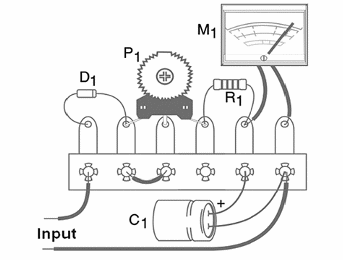
The few components used in this project can be soldered to a terminal strip as figure 2 shows. Be careful with the position of polarized components, such as the diode, meter and C1.

The device is housed in a small plastic box or, if you prefer, installed in the front of the equipment to where it will be plugged. It is up to the reader to decide the best way to use it. The diode can be replaced by equivalents, like the 1N4148 or 1N4007. The trimmer Potentiometer is common and the resistor is a 1/8 W or 1/4 W with any tolerance.
The indicator response speed is given by the capacitor. The reader can test the value that gives the best performance, according to the application. Values between 1 µF and 100 µF can be tested. We recommend the reader to conduct tests to match the capacitor with the meter characteristics. The working voltage for the capacitor is 12 V or more.
Adjusting is very easy. Plug points A and B to the output of any sound amplifier (wires to the loudspeakers). Then, with some music or another program running, adjust P1 to get the balance of the indicator. If you note that the indicator moves to the wrong direction, change the wires to the meter.
D1—1N4002 or equivalent—silicon diode
P1—47 kΩ—trimmer Potentiometer
R1—1 kΩ x 1/8 W—resistor—brown, black, red
C1—1 to 47 uF x 12 V—electrolytic capacitor
M1—0-200 uA—meter—see previous text


