The sensivity of most moderately-priced AM receivers is poor in the medium-wave band. Worse yet, selectivity alSo drops off sharply within the upper part of the band, making the receiver highly susceptible to images, noise and annoying heterodynes.
Even the best antenna and a good booster amplifier can't make up for these deficiencies in a common receivefs front end.
But, using an RF preselector between the antenna and the receiver's antenna input terminals wiII give you real increase in the reception quality.
This circuit matches the antenna impedance \with the receivers antenna input according the frequency of the tuned station.
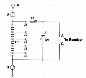
Figure 1 shows schematic diagram of the Medium-Wave Preselector.

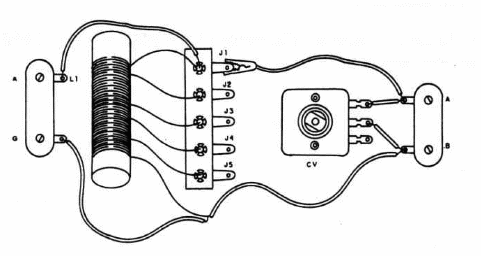
Figure 2 shows an exploded view of the circuit, which can be housed in a small plastic box.

L1 is formed by turns of No. 28 enameled wire, wound on a 5/16-inch ferrite form.
Taps are made each 15 or 20 turns and its number is not criticaL The number of taps can be altered.
Attach your antenna and ground to the input terminals of the preselector.
Tune to the desired station on your receiver, and, by choosing the best position of the alligator clip on the strip and by adjusting CV, find the best signal.
The required antenna wilI depend upon the station yqu want to tune.
A random length of wire will give fairly good performance through the AM band.
Antennas with lengths between 15 and 150 feet are recommended for best performance.
Medium-Wave RF Preselector
L1 - Medium-Wave Coil - see text
CV - 365 pF miniature variable capacitor
X1 - Alligator cüp
2-position barrier strip
Ideas to Explore
To learn more about the circuit and devices:
Explain the importance of a good ground connection in this circuit.
What is the meaning of “impedance'?
Use a new coil with 20 turns and taps every'3 turns to tune shortwave stations.
Make a second coil (20 turns) on the same ferrite .rod to plug the antenna and ground
Obs. This circuit is part of the author’s book Fun Projects for the Experimenter – TAB Books – 1998


