This project uses a strange way to get its power. It uses power “extracted” from the tuned station to give to the amplifier transistor.
With a reasonably strong applied modulation envelope, this type of detector produces a strong demodulated output.
Naturally, the closer you are to a strong station, the more current your radio will be able to supply.
For best results, you must do everything possible to deliver a strong signal to the transistor detector.
We recommend a good antenna and ground, the latter preferably being made to a water pipe or solid external ground composed of a pipe driven at Ieast 5 feet into moist earth. This is important for ensuring maximum signal pickup.
If you have plenty of space available, the Ionger the antenna (up to about 100 feet), the better the results.
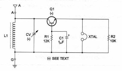
Figure 1 shows the schematic diagram of the Free-Power AM receiver.

Observe that the heart of the circuit is a germanium transistor that works as a detector and audio amplifier.
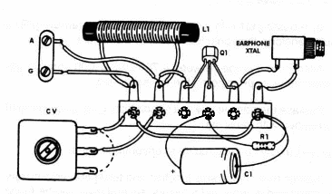
Components placementíon a terminal strip used as a chassis is shown in figure 2.

The terminal strip can be fixed on an experiment board that can be constructed using some common tools and materials.
Q1 is any germanium transistor, such as GE-2. or 2N107.You can find germanium transistors in old nonworking AM transistor radio receivers.
Nonworking AM radios can also supply the variable capacitor and the Ioopstick (ferrite rod).
Earphone must be a high-impedance crystal type. Low-impedance earphones don´t ot function in this circuit.
Free-Power AM Receiver
Q1 - NPN or PNP germanium transistor - see text
XTAL - Crystal earphone
L1 - Loopstick - see text
CV - 365 pF variable capacitor - see text
R1 - 12,000 ohm, ¼ W, 5% resistor
C1 - 1 µF, 25 WVDC electrolytic capacitor
ldeas to Explore
To learn more about the circuit:
Replace L1 by 15 turns of No. 28 wire, wound on a ferrite rod, to tune short-wave stations.
By replacing Q1 with a germanium diode and removing R1 and C1 you'll transform this radio into a simple crystal set.
Alter R1 in a range between 4,700 and 47,000 Ω to get better performance, depending on the transistor used.
Replace the transistor with .a silicon type, such as the BCS48. What will happen with sensivity?
Science project involving the circuit and uncommon uses:
Explain how crystal sets function and tell about radio history. If you are interested in more radio history, several texts can be found in our site and the internet.
lf you want to leam more about radio receivers, try to find information about heterodyne and super-hereterodyne types.
Note: This circuit is part of the author’s book Fun Projects for the Experimenter – TAB Books – 1998


