Dogs, mice, bats and other animals can hear sounds with frequencies up to 40,000 Hz.
There are several kinds of insects that can also hear or react to these sounds.
The circuit we propose here produces a continuous sound emission in frequencies above the human Iimit, or a range between 18,000 and 40,000 Hz.
These sounds are called ultrasounds and can be used in several experimental and practical applications.
The device we describe here can be used to scare dogs and other animals, in biological experiments, and many other interesting applications.
The recommended piezoelectric transducer has its máximum output power between 700 and 3,000 Hz, but it also will operate at higher frequencies emitting less power.
The recommended power supply is four AA cells or a 9-volt battery.
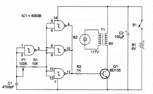
Our project runs between approximately 18,000 and 40,000 Hz, but you can easily alter this range by changing C1, in a range between 470 pF and 0.001 uF.
Frequency can be set by P1 in the range determined by C1. Remember that the 40938 IC will oscillate in frequencies up to 500 kHz.
The complete circuit of the Ultrasonic Generator, using the four gates of a 4093B integrated circuit, is shown in Figure 1.

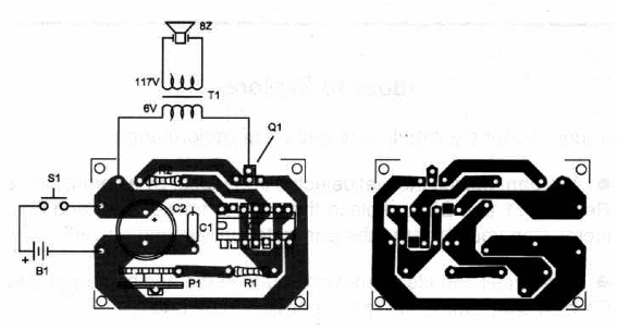
Components placement on a printed-circuit board is shown in Fígure 2.

The circuit can be housed in a small plaàtic box and the transducer will be fixed in the front panel.
Take care with the position of the polarized parts, such as the transistor, electrolytic capacitor and power supply.
For continuous operation, Q1 should be mounted on a heatsink.
The transformer is not a critical part. Any transformer with a sécondary coil ranging from 100 to 500 mA can be used in this project.
Ultrasonic Generator
IC1 - 40933 CMOS lntegrated circuit
Q1 - BD135 medium-power NPN silicon transistor
BZ - Piezoelectric transducer Radio Shack 273-090 or equivalent
T1 – Transformer: primary 117 VAC; secondary 6 Vx100 mA
R1 - 10,000 ohm, ¼ W, 5% resistor
R2 - 1,000 ohm, ¼ W, 5% resistor
P1 - 100,000 ohm trimmer potentiometer
C1 - 4,700 pF ceramic or metal film capacitor
C2 - 100 µFx 12 WVDC electrolytic capacitor
S1 - SPST toggle or slide switch
B1 - 6V or 9V - AA cells or battery - see text
Ideas to Explore
To Iearn more about the circuit or to get better performance:
You can replace the piezoelectric tranSducer by a common tweeter. Remove T1 and BZ and place the tweeter between S1 and Q1's colIector. Can you measurethe generated ultrasound power?
The Circuit can also generate sound Àin the audible range. Replace C1 by a capacitor in the range between 0.02 and 0.1 µF.
Explain ultrasounds and how they are produced by electronic transducers.
What is a piezoelectric material?
Science and different applications:
Several experiments-can be made using ultrasounds. You can experiment with dog conditioning. Using this oscillator you can call a dog using an inaudible sound! (inaudible to humans)
Choose a capacitor between 0.01 and 0.047,uF to produce sounds both in the audio range and ultrasound range. You can now conduct experiments to determine the exact upper-limit frequency heard by humans. You also can conduct experiments with animals. It will be important to have a frequency counter on hand to do this work.
o Replace BZ by electrodes. The circuit wiII generate a high-voltage output that can be used in nerve stimulation. Use a 10,000 ohm potentiometer to adjust output voltage at this point. Pulses can reach peaks as high as 400 volts.
To get pulses (for nerve stimulation and other experiments) you only have to replace C1 with a 1 µF capacitor and P1 with a 1,000,000 ohm potentiometer. Pulses in the rate range between 0.1 per second to 10 per second can be generated with this change.
This circuit can also be used as a fluorescent Iamp inverter. A common fluorescent Iamp (4 to 20 watts) in place of the transducer wiII glow, even one that is weak enough to not function on the AC power Iine.
Note: This circuit is part of the author’s book Fun Projects for the Experimenter Vol1 – TAB Books – 1998


