This high-power version of an audio oscillator produces a strong audible tone using a piezoelectric transducer.
All four gates existing in the 4093 IC are used in this project to drive the transducer with a good audio signal.
The circuit can be used in alarms, toys, as a standalone project to teach about oscillators specifically, or in experiments using continuous sounds in the frequency range between 100 and 10,000 Hz.
The recommended piezoelectric transducer emits maximum output power between 700 and 3,000 Hz, but it will also operate in other frequencies with Iess power.
Power supply voltage range is between 5 and 12 volts.
Current requirements depend upon the power supply voltage, ranging from 10 to 50 mA typically.
P1 adjusts the tone frequency. C1 can be altered within a Iarge range of values as indicated in the schematic diagram, shown in Flgure 1.

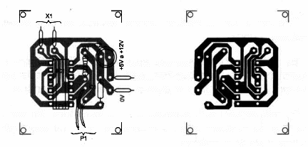
Components placement on a printed-circuit board is shown in Flgure 2.

You can also mount the circuit using a solderless board for experimental applications.
AII the components and the batteries (if used as power supply) can be housed in a small plastic box. BZ can be replaced with a common piezoelectric tweeter.
But, in this case, you should open the tweeter and remove the small transformer from inside it.
Then the output of the circuit should be oonnected directly to the small piezo-electric transducer.
Power Audio Osclllator
IC1 - 40933 CMOS integrated circuit
BZ - Piezoelectric transducer
(Radio Shack 273-090 or equivalent)
P1 - 100,000 ohm potentiometer
R1 - 10,000 ohm, 1/4W, 5% resistor
C1 - 1200 pF to 0.047 µF ceramic or metal film capacitor
Ideas to Explore
To Iearn more about oomponents and devices
This circuit can also produce sound in the ultrasound band. Using a 1,200 pF capacitor for C1, the range will reach an upper Iimit of about 100,000 Hz.
Explain how a push-pull output stage operates.
Science and uncommon applications:
This circuit can be used for animal conditioning or in experiments involving sounds.
O By replacing P1 with sensors, such as LDRs (Light Dependent Resistors) or NTCs (Negative-Temperature Coefficient resistors), tone frequency will be Iight-dependent or temperature-dependent.
By replacing P1 with touch sensors or electrodes, we can use the circuit as Iier detector or bio-feedback devices. The sound pitch will depend upon skin resistance.
The circuit can also be used as a fish attractor or in experiments involving water animals and sounds. Replacing BZ with wires immersed into water will generate electric current fields for experimental worksinvolving the influence of these fields on fish or other beings.
Some animals, such as mice and rats, are scared off by ultrasounds.The circuit can be used in experiments to determine the frequencies that are more effective for this task.
See other projects involving sounds in this site for new ideas to explore.
Note: This circuit is part of the author’s book Fun Projects for the Experimenter Vol1 – TAB Books – 1998 (link para download)


