Small home appliances and circuíts can be turned on after a time delay ranging from seconds to minutes using this simple timer.
School and hobbyist experiments can be time-controlled by using this circuit.
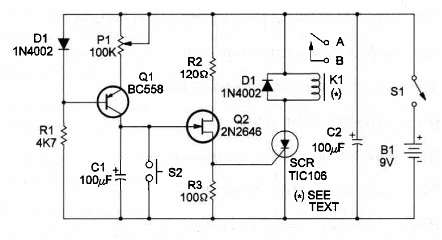
The unit has a constant-current source to charge C1. C1 and P1 adjust the time range.You can alter
C1 wíthin a range of 100 and 1000 µF to change the time range.
Using a 1 ampere relay you can oontrol AC Ioads up to 100 watts wired to the 117 VAC power Iine.
To operate the unit, connect the load to the relay contacts (points A and B, used as a switch) and adjust P1 to the desired time delay.
Press S2 do discharge C1 completely .
Then close S1 to start. After the adjusted time delay, the relay will close, and the load wiIl be powered ON.
Conversely, by using the NC (Normally Closed) contacts of the relay you can turn a device OFF after the adjusted time.
To use the unit again you must press SZ to discharge C1 before starting.
Figure 1 shows the schematic diagram of the timer.

Observe the dífferent components used in this project a unijunction transistor (UJT) and an SCR (Silicon Controlled Rectifier).
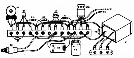
A mechanical view is shown in Figure 2, using a terminal strip as chassis.

AII the components and power supply can be housed in a small plastic box.
Take care with positions of critical components, such as the UJT, SCR, diodes and electrolytic capacitors.
The relay depends upon the power supply voltage and voltage drop through the SCR.
This drop is about 2 volts, so you need to use 6 to 7.5-volt relays with a 9-volt power supply.
The SCR needn't be mounted on a heatsink, as the current drain is Iow.
Use AA cells or a DC power supply to power this timer.
Remember that current drain is low only when the relay is off.
Timer
Q1 - BCS48 NPN general-purpose silicon transistor
Q2 - 2N2646 unijunction transistor
SCR - TIC106 silicon controlled rectifier
D1,D2 - 1N4002 silicon diodes
R1 - 47,000 ohm, ¼ W, 5% resistor
R2 - 120 ohm, ¼ W, 5% resistor
R3 - 100 ohm, ¼ W, 5% resistor
P1 - 100,000 ohm potentiometer
C1, 2 - 100 µF, 12 WVDC electrolytic capacitors
K1 - Relay - see text
S1 - SPST slide or toggle switch
S2 - Normally Open momentary switch
B1 - 9V - six AA cells
Ideas to Explore
To Iearn much about circuit and devices or to get better performance:
Explain how a constant-current source operates.
Explain how a UJT and SCR operate.
Alter C1 to get higher time delays. Try values up to 1,000 µF.
Science projects and uncommon uses for this device:
All experiments that need time-delay control can use this device, as !ong as the time delay needed falls in the range of this timer (between a few seconds and minutes). Use a oommon watch as reference to make a scale for the potentiometer.
The circuit can be used to activate dangerous experiments with a safe time-delay allowing the experimenter to reach safe distance.
Traps can be armed after a time-delay, so the experimenter can avoid the trap himself.
Chemical processes can be controlled using this timer. Any audio oscillator described in this book can be use as waming circuit when wired to the relay output.
Note: This circuit is part of the author’s book Fun Projects for the Experimenter Vol1 – TAB Books – 1998 (link para download)


