Under what conditions can you need a heat exhaust detector?
Of course, one of the ways you have to detect the escape of gas is to get your hand closer to the place. The jet of hot gas will surely be noticed.
While this is a simple example, there are cases where the detection of gas escape by the method of approaching the hand or putting the finger in place is dangerous or difficult.
It is dangerous in cases where nearby objects are hot presenting the danger of burns or connected to high voltage sources presenting the danger of shocks; difficult in the case where your fingers or hand cannot reach the desired location.
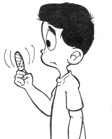
To avoid the danger of burns in the detection of heating points, hot air or cold drain pipes, gas exhaust, we give this article a useful electronic instrument.
It is a fast detector of temperature variations. Assembled in a small box or remote board, this instrument accuses the movement of an instrument needle of heat or cold leaks, heating or cooling components.
In addition to domestic applications, this appliance has a wide variety of utilities in industrial electronics. You can use it for the following purposes:
- Detection of exhaust in air conditioning and refrigeration systems.
- Detection of steam exhaust in machines
- Detection of overheating points in machines.
- Detection of overheating in electronic components (Figure 2).
- Detection of air streams in halls and residences.
- Detection of chimney operation.
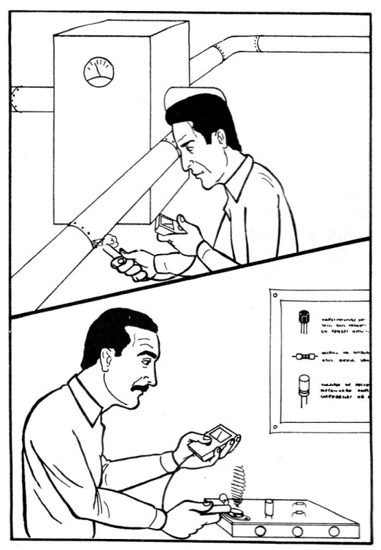
Extremely simple to assemble and use, this detector uses a single 9 V battery as the power source. The battery life is very high due to its low consumption.
HOW IT WORKS
The basic element of this detector is the sensor made with a common silicon diode of type BA315. This component, whose aspect and symbol are shown in Figure 3, works as follows in this function: when polarized in the reverse direction, it lets a small current (leakage current) circulate which depends on the temperature of its junction.
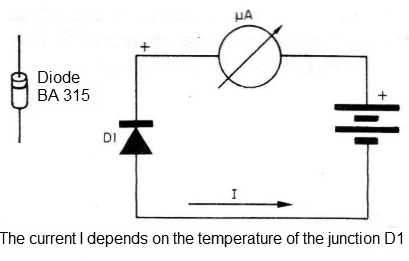
As the temperature increases, charge carriers are released and the current increases its intensity. Likewise, when the temperature decreases, the charge carriers are reduced, and consequently the current flowing through the component.
The reduced size of the diode with a small thermal capacity for the housing allows a relatively large readiness for the detector, ie, it acts very fast (the speed of action of a sensor of this type is linked to the time it takes to change heat with the environment and therefore have its temperature balanced).
Like the current obtained from the diode under conditions of detecting temperature variations, it is necessary to use a transistor as an amplifier element to be able to conveniently drive the indicating instrument.
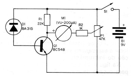
In this circuit, the transistor acts as the arm of a bridge that has its equilibrium adjustment determined by the position of the potentiometer cursor, as shown in Figure 4.
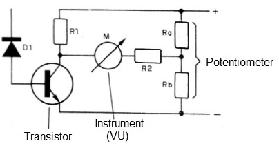
The indicator instrument, with its needle placed in the middle of the scale, can detect temperature variations in any direction. The positive temperature variations corresponding to the sensor heating cause the needle to deflect to the left, while negative variations corresponding to sensor cooling cause the needle to deflect to the right.
Of course, an instrument of zero can be used in the middle of the scale for greater accuracy or adjustment at one end to obtain indication of only one type of variation.
The sensor used can detect temperatures up to 120 degrees Celsius without problems.
MATERIAL
All components used in this assembly can be easily obtained, including the case for the portable version which can be made of plastic with the measurements shown in Figure 5.
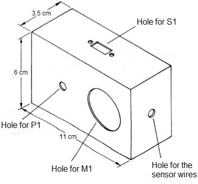
This box should be able to house the indicating instrument on its front. For the board assembling, simply fit the front dimensions to the available space.
We start with the instrument which is the highly sensitive mobile coil type. A standard 200UA VU-meter was used in the prototype assembly which can be achieved at a relatively low cost in any electronic material house.
This is the most expensive component of the assembly and it can be said that its price corresponds to more than 50% of the whole appliance.
The transistor used may be the BC548, as the material list asks, but there are several direct equivalents which can be used: BC237, BC238, BC239, BC548, BC549, etc.
The transistor must be of good quality with a minimum of leakage current (ICEo), because if problems occur, it will be difficult to achieve zero adjustment of the device.
The leakage current can be measured with the aid of the multimeter connected to the highest resistance scale. The probes are then pressed against the collector and transmitter (the base is switched off).
This current shall be such that the resistance measurement is greater than 2 M ohms.
The sensor used was a BA315 diode. Although other types of silicon diodes can be tested in this function, of all we have seen, this gave the best results in view of their readiness and sensitivity.
The adjustment potentiometer is 47 k and a simple (lin or log) can be used if the reader opts for a separate general switch, as in the original, or with key if the on and off operation is combined with the setting.
The resistors are 1/8 W with the values indicated on the material list. In the absence of 1/8 W resistors with the given values, larger ones such as ¼ W, or even ½ W, may be used without impairing the operation of the detector.
The values of the resistors are given by the colored rings in their enclosure.
We still have the switch and the battery which are common. The switch must be of one type according to the board of the apparatus, and for the battery you will need to use a connector and a clamp for fixing.
Complete the material a plastic knob for the potentiometer, the terminal bridge to be cut into the appropriate size, in addition to the ballpoint pen tube, used for fixing the sensor (portable version), wires, welding, screws, etc.
ASSEMBLY
The welding of the components in the terminal bridge must be done with a small power welder with a thin tip, with a maximum of 30 W of power.
Additional tools for your job are: a side cutter, thin-nose pliers and screwdrivers.
Start preparing the housing or board (according to your version) with the drilling according to the instrument, the potentiometer, the main switch and possibly the sensor wire output. A hole of approximately 3 mm should be left for the sensor to pass through the wires.
The complete diagram of the detector is shown in Figure 6, where the components and connections are represented by their symbols (try to familiarize yourself with the symbology adopted in electronics and the interpretation of diagrams like this).
In Figure 7, we have the assembly on the terminal strip.
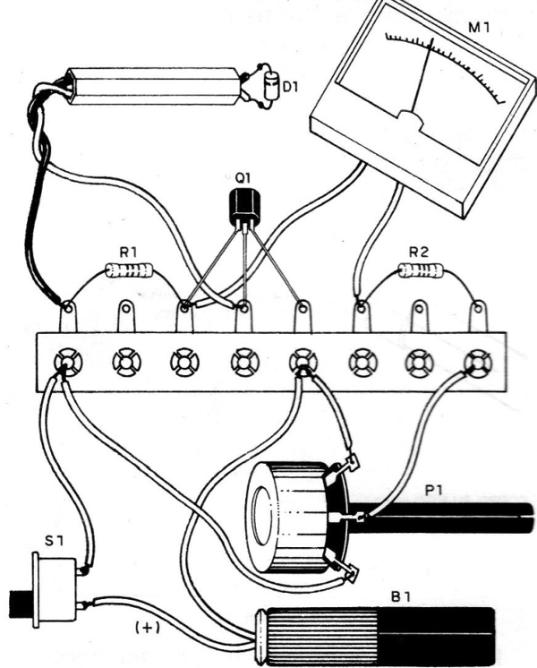
The sequence of operations with the main care in the assembly is as follows:
a) First weld the transistor observing that its flat part should face up. Welding should be quick so that the heat does not propagate through the terminal to the body of the component and this can cause damage. Hold the terminal with the thin-nose pliers to prevent this spread if the welding is slow.
b) Weld the resistors by observing their values which are given by the colors of the rings. Be quick in welding .To put them on the bridge cut a piece of their terminals. Make them fit the bridge as shown in the figure.
c) Attach the potentiometer to the housing or board, welding the wires from this component to the terminal bridge. These wires should be wrapped and flexible. Their length should not exceed 15 cm. If the potentiometer has a long shaft, cut it to the appropriate length before assembling.
d) Set the instrument to the panel, also welding the connecting wires which should be of plastic cover and not for too long. Be careful when welding the wires to the instrument terminals, as excess heat can damage the plastic housing. Be quick.
e) Weld the wires of the battery connector to the switch and the terminal bridge observing their polarity. The black wire is usually the negative going to the terminal bridge and the red wire is positive, going to S1, which should be attached to the box. From S1, pull a wire to the terminal bridge.
f) Attach the terminal bridge to the enclosure or board. To keep all components firm after closing the box (which will be done after the sensor connection) you can use a piece of plastic foam. Another solution is to screw the terminal bridge itself to the desired location.
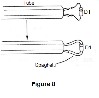
g) For the sensor, you must pass two wires of different colors through the ball point tube if your version is for portable use. The wire attached on the side of the diode ring will be welded to the first terminal of the bridge (R1), while the wire connected on the non-ring side (anode) goes to the base of the transistor (Q1). This pair of wires should be no more than 1 meter in length.
For the remote version, a shielded cable up to 20 meters in length may be used. The cable mesh will be attached to the side of the diode anode and the center wire to the cathode (ring side).
A piece of "spaghetti" that is nothing more than ordinary wire cover works to insulate the sensor terminals, as shown in Figure 8.
Completing the assembly, check all the connections and if everything is in order, before closing the box or installing the panel, make a functional test.
TEST AND USE
Put the connector on the battery and turn on the S1 switch.
Turn the adjustment potentiometer until the device marks a value corresponding to half the scale (Figure 9).
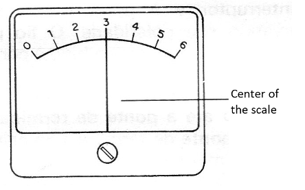
This will be the reference point of the detector, and the reader can make a mark for its identification.
If it is not possible to obtain the zero point in question, reverse the device connection, ie, replace its wiring. If still, adjustment is not achieved, replace transistor Q1 with another one of the same type, as it is likely to leak.
Do not throw away the transistor as it can be used in another assembly.
With the instrument set to the center of the scale, move the sensor closer to your mouth and release a puff of warm air, as shown in Figure 10.
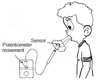
The instrument needle should immediately indicate this temperature change.
In order to use the device in its portable version, it is only necessary to bring the sensor closer to the places where it is desired to detect possible variations of temperature by the exhaust of hot air, gases, etc.
In the case of heated components, simply push the sensor in place and wait a few seconds for the device indicator.
In Figure 11, we give some suggestions for the remote installation case.
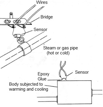
The sensor, in this case the diode, can be assembled in the vicinity of the point of suspicion or to be monitored, or placed in contact with the point at which it is desired to control the heating or cooling.
Q1 - BC548 or equivalent (BC237, BC239, BC547, BC549, etc.)
D1 - Diode BA315
MI - 200 uA common VU meter - any type
P1 - 47 k - potentiometer (if used with a key, delete S1)
R1 - 22k x 1/8 W- resistor (red, red, orange)
R2 - 1 k x 1/8 W - resistor (brown, black, red)
S1 - Single switch
B1 - 9 V battery
Miscellaneous: insulated terminal bridge, mounting box, ball point pen for sensor placement, connector for 9V battery, wires, screws, welding, etc.


