Metal detectors are circuits that always arouse the curiosity of assemblers.
However, many are deluded by the possibility of finding deep buried treasures or even of detecting very small objects at great distance beneath the earth. What happens is that the working principle of most detectors is such that it only makes them useful in the cases indicated in our introduction.
Thus, the small detector we described in this article can be mounted in a small plastic box and used efficiently to find small objects in carpets or under the sand and metal plumbing and wires embedded in walls.
Installing electricians, Structured Cabling professionals and even building maintenance personnel will enjoy the usefulness of this device in not drilling a wall where it already passes a conduit or locating the passage of wires that are not indicated on a plant.
Another interesting application for this circuit is shown in figure 1 where it is used to search a person for possible detection of weapons and dangerous objects or even metal objects that may be being stolen.
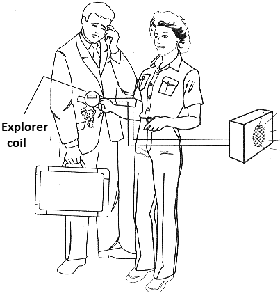
The circuit can be powered by both standard and 9V battery and its consumption is relatively low which greatly extends the range of the source.
HOW IT WORKS
The operating principle of this detector is the same as most commercial equivalents: frequency beating. If we have two oscillators operating on the same frequency, mixing their signals as shown in figure 2, the result will be a zero beat.
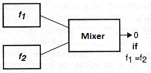
This means that in these conditions, we will have no exit signal.
Let us suppose that one of the oscillators generates a fixed frequency signal, but that the other has the frequency of its signal determined by an LC circuit, where L is an exploratory coil. Any metal object entering the field of the coil L will alter its inductance by concentrating or scattering the lines of the magnetic field. This means that the frequency of the oscillator changes whenever an object enters the field of action of its coil.
The end result of this is that the frequencies of the two oscillators will no longer be equal. By then mixing the two signals, the beat will no longer be null. At the output of the circuit we will have two signals: one whose frequency is the sum of the frequencies of the oscillators and therefore of very high value. The other will be the difference of the signal frequencies of the two oscillators.
As this difference signal tends to a frequency in the audio range, if it is amplified and applied to a transducer we will have a "whistle". Thus, whenever any object enters the field of the explorer coil, the frequency change will translate into production of a whistle on the transducer.
The greater the influence of this object in the field of the coil, the greater the frequency difference between the two oscillators and therefore the higher the sound produced. In our practical circuit the two oscillators are built around two ports of a 4093 integrated circuit. In an oscillator we have an explorer coil and a capacitor of adjustment that allows to "zero" the beat, and in the other we have a coil and a fixed capacitor.
The other two ports of the integrated circuit are used to mix and amplify the difference signal by applying it to a transducer.
ASSEMBLY
In figure 3 we have the complete diagram of our metal detector.
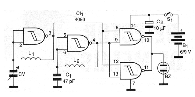
The arrangement of the components on a printed circuit board is shown in figure 4.
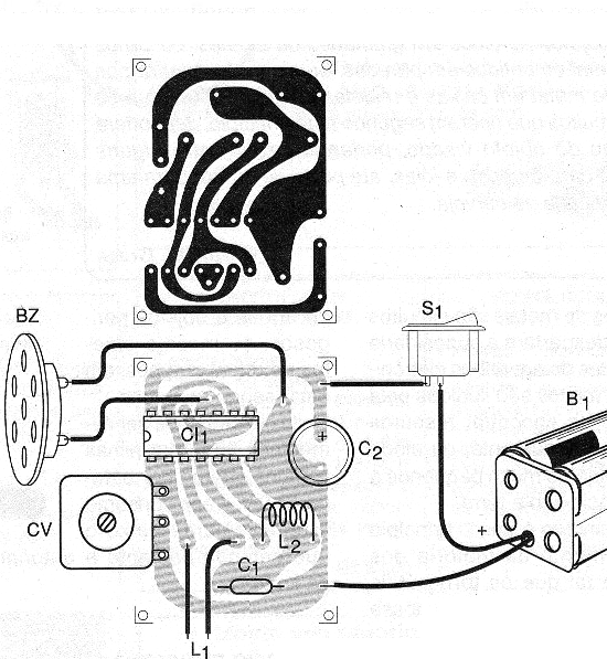
The most critical point of the assembly is the take-up reel which can be mounted in a plastic or even cardboard form with the approximate dimensions of figure 5.
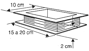
This coil can be glued directly under the detector case in case your circuit connection does not need to be made with special wires.
However, if the coil is mounted further on a cable to hold, for example, it will need to be connected to the circuit via shielded cable. This coil is formed by 30 to 40 turns of 26 or 28 AWG enameled wire.
The adjusting capacitor can be used from an unused transistor radio. Any variable capacitor from 120 to 400 pF of maximum capacitance can be used.
RF shock can be both commercial and convoluted. For this, wrap 40 to 60 turns of enameled wire 32 or thicker in a small ferrite rod. See that the equilibrium of the circuit, that is, the obtaining of the null point depends fundamentally on these components.
Depending on the construction that the player makes it may be necessary to try some changes in the coils to be able to clear the circuit. How to do this we will see later. The transducer used is of high impedance ceramic type.
TEST AND USE
Turning on the device and moving the control of CV we must get increasingly serious sounds until at some point it stops. Then approaching any small metal object from the explorer coil, the circuit should "beep" or emit sound.
If the control reaches the end of its stroke before zero is reached, the coil L1 must be changed. If the control reaches its lowest point with the variable all open it will be necessary to decrease the number of turns of L1.
If it reaches its lowest point all closed, it will be necessary to increase the number of turns of L1. To use the device set null (obtain the null point in CV).
Then, just approach the explorer coil from where it is suspected to be metal.
Do not install the device in a metal case so that it does not disturb the circuit or cause false detections.
Semiconductors:
CI-1 - 4093B - CMOS integrated circuit
Capacitors:
CV - variable capacitor - see text
C1 - 47 pF - ceramic capacitor
C2 - 10 uF / 12V - electrolytic capacitor
Several:
L1 - Scroll coil - see text
L2 - 47 uH - microchoke - see text
BZ - Piezoelectric transducer
S1 – On/Off switch
B1 - 6 or 9V - 4 batteries or battery
Printed circuit board, enameled wires and shape for coils, battery holder or battery connector, mounting box, wires, solder.


