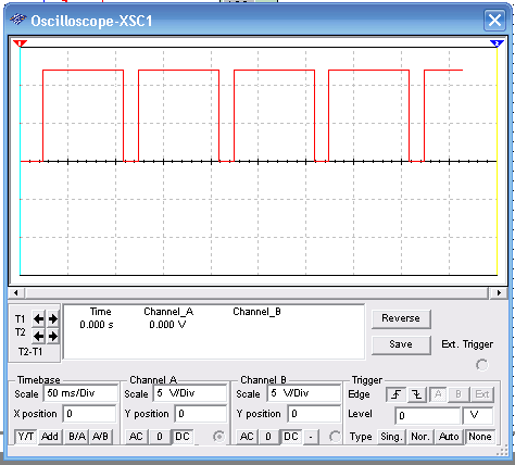
This is a basic astable circuit using the 555 IC and driving two LEDs. The phase on a rate giving by R3, R4 and C1. These components can be changed in the simulation. Figure bellow shows the signal generated by the circuit displayed in the virtual oscilloscope of the MultiSIM.
Duty-cycle can be changed altering the ratio between R3 and R4. Figure bellow shows the simulation. Observe the adjustments for the oscilloscope for correct display of the waveshapes.

A frequency control can be added replacing R4 by a 1 M ohm potentiometer in series with a 10 k ohm resistor.
To download the simulation files and Netlist - click here (ni0006.zip)


