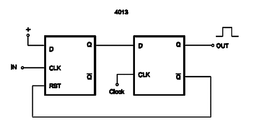
The circuit shown here generates one clock interval when a positive transition command pulse is applied to its input. The circuit is intended for applications where the synchronization of a circuit is important. The waveforms shown in the figure offer a better idea about the function of this circuit. The first flip-flop is used to cancel the difference of time between the arrival of a signal and the edge of the system clock. The second flip-flop is used to generate a pulse clock with a constant duration that will also resets the first stage.


