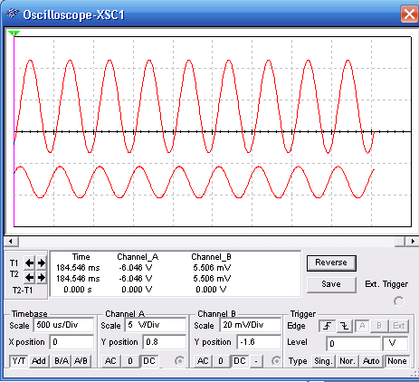
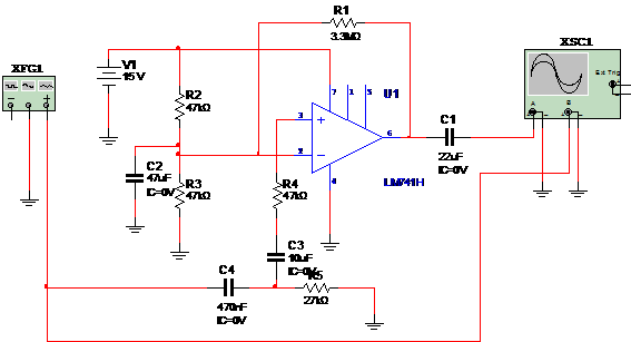
This simple circuit presents a voltage gain of about 1,500. The input impedance is high and the output impedance is low. A 12 Vpp signal can be sourced when a 20 mV signal is applied to the input. The gain depends on the ratio between R4 and R1. Different gain can be achieved if R1 is changed. Figure bellow shows the input and output signals displayed in the virtual oscilloscope of the MultiSIM

Bellow the simulation. Observe the adjustments for the function generator.

To download the simulation files and Netlist - click here (ni0004.zip)


